
Speaker device

a technology of speaker and speaker body, which is applied in the direction of transducer details, electrical transducers, electrical apparatus, etc., can solve the problems of relative deterioration of the quality of the reproduced sound, relative difficulty in managing a thinner and larger sound volume loudspeaker, etc., and achieves simple structure, simple configuration, and simple structure

Active Publication Date: 2011-03-24
PIONEER CORP +1
View PDF3 Cites 28 Cited by
  • Summary
  • Abstract
  • Description
  • Claims
  • Application Information

AI Technical Summary

Benefits of technology

The present invention provides a flat speaker device that can produce a loud and high-quality sound with a simple structure. The device includes a diaphragm, a frame, a magnetic circuit, and a driving member. The driving member includes a voice coil and a driving part that moves in a different direction than the diaphragm. The device also has an angle conversion and transmission part that connects to both the driving part and the diaphragm at an angle, allowing for the efficient transfer of sound waves. Overall, this invention provides a simple yet effective flat speaker device that can produce superior sound quality.

Problems solved by technology

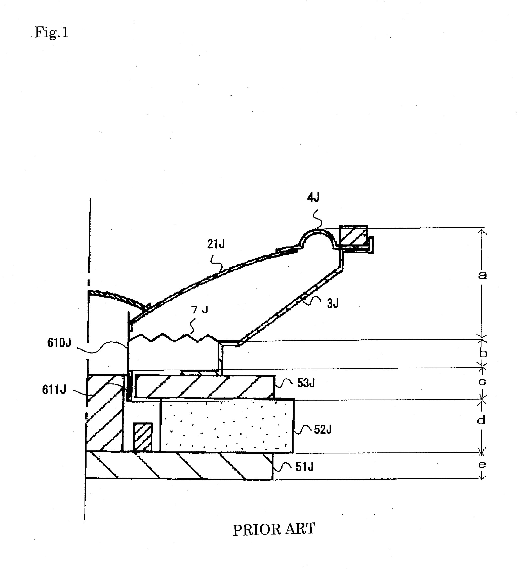
That is, since the above mentioned speaker device is configured such that the vibration direction of the voice coil bobbin 610J and the vibration direction of the diaphragm 21J become substantially parallel, it is relatively difficult to manage a thinner and larger sound-volume loudspeaker.
In the above mentioned electrostatic speaker device, however, if an audio signal of relatively large amplitude is input, a driving force may nonlinearly vary considerably and thereby quality of a reproduced sound may be relatively deteriorated.

Method used


Image

  • Speaker device
  • Speaker device
  • Speaker device

Examples


first embodiment

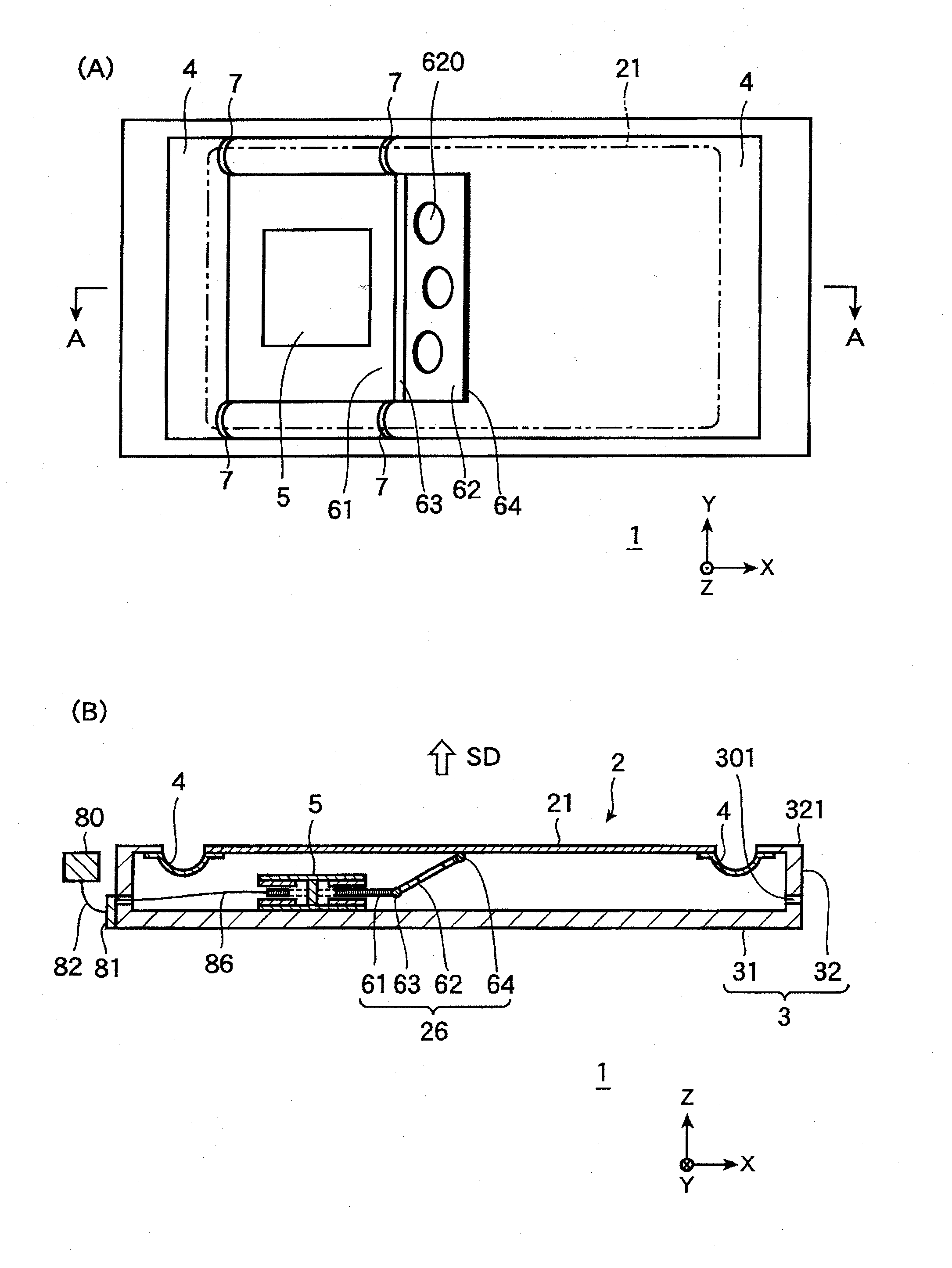
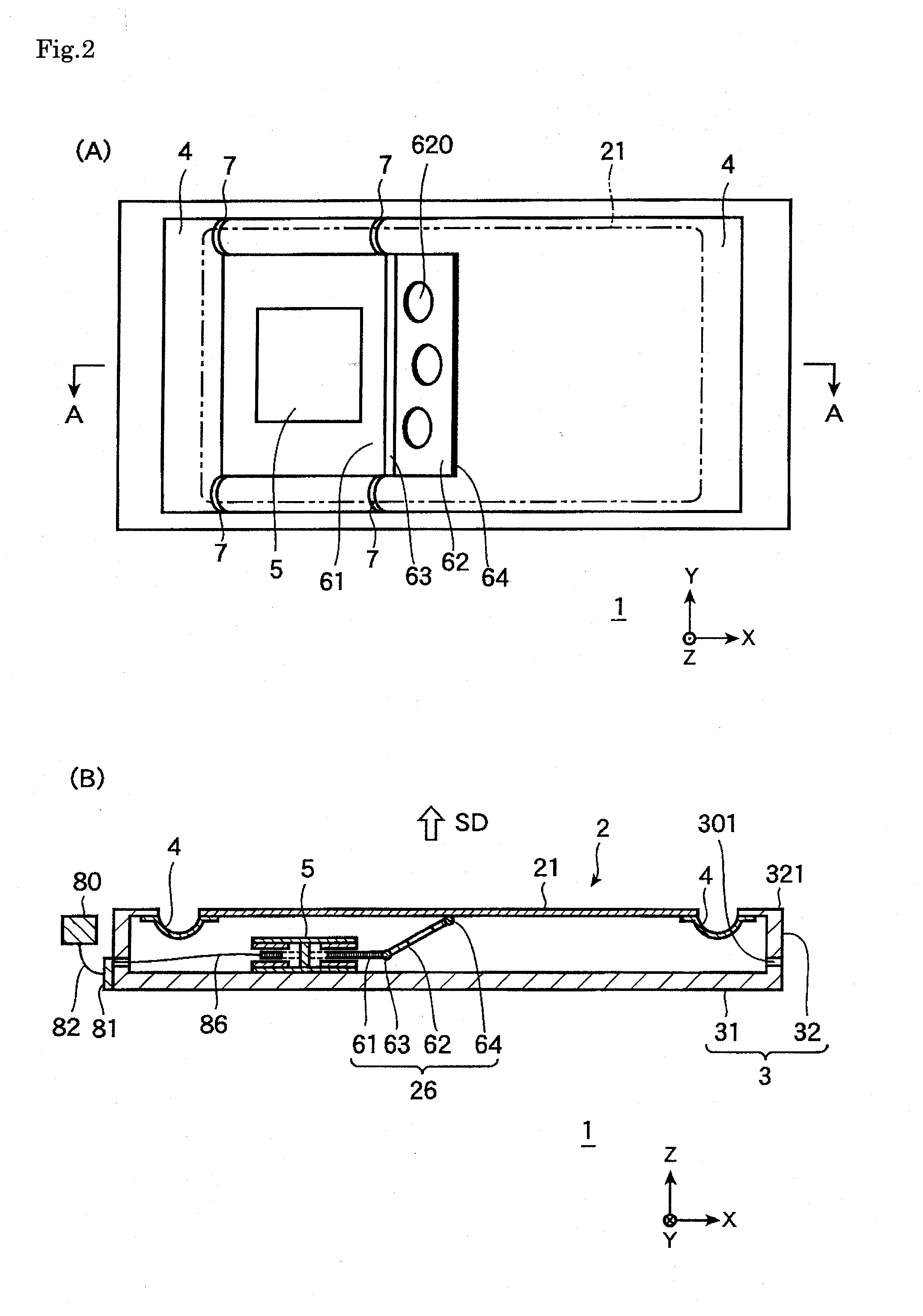
[0042]FIGS. 2A and 2B are diagrams illustrating the speaker device 1 according to a first embodiment of the present invention. Specifically, FIG. 2A is a front view of the speaker device 1 according to the first embodiment of the invention (the diaphragm is not shown) and FIG. 2B is a cross-sectional view of the speaker device 1 shown in FIG. 2A taken along the A-A line.

[0043]FIG. 3 is an enlarged perspective view of the vicinity of the magnetic circuit 5 of the speaker device 1 shown in FIGS. 2A and 2B. FIG. 4 is an exploded perspective view of the magnetic circuit 5 of the speaker device 1 shown in FIG. 3. FIG. 5 is a cross-sectional view of the speaker device 1 shown in FIGS. 2A and 2B. The sound emission direction (SD) of the diaphragm 21 of the speaker device 1 is defined as Z-axis direction, the lengthwise direction (driving direction of the driving part) as X-axis direction, and the direction perpendicular to the Z-axis and the X-axis as Y-axis direction.

[0044]As shown in FIG...

second embodiment

[0120]FIGS. 7A to 7C illustrate the speaker device 1A according to a second embodiment of the present invention. Specifically, FIG. 7A is a cross-sectional view of the speaker device 1A when the diaphragm is not displaced with respect to a reference position. FIG. 7B is a cross-sectional view of the speaker device 1A when the diaphragm is displaced to the sound emission side with respect to the reference position. FIG. 7C is a cross-sectional view of the speaker device 1A when the diaphragm is displaced to the side opposite of the sound emission side. The same configurations in the first embodiment are not described here.

[0121]The speaker device 1A of this embodiment includes plural magnetic circuits and driving members, specifically two magnetic circuits 5A and 5B and two driving members 26A and 26B. The driving member 26A includes a driving part 61A in which a voice coil is formed, an angle conversion and transmission part 62A, a folding part 63A, a folding part 64A, whereas the d...

third embodiment

[0128]FIGS. 8A to 8C are diagrams illustrating a speaker device 1B according to a third embodiment of the present invention. Specifically, FIG. 8A is a cross-sectional view of the speaker device 1B when a diaphragm is not displaced with respect to a reference position. FIG. 8B is a cross-sectional view of the speaker device 1B when the diaphragm is displaced to the sound emission side with respect to the reference position. FIG. 8C is a cross-sectional view of the speaker device 1B when the diaphragm is displaced on the side opposite of the sound emission side with respect to the reference position. The same configurations in the first and second embodiments are not described here.

[0129]As shown in FIGS. 8A to 8C, in the speaker device 1B of this embodiment, the angle conversion and transmission parts 62A and 62B are foldably joined to the central portion (barycentric position) of the diaphragm 21. Also, compared with the second embodiment, the magnetic circuits 5A and 5B are arrang...


PUM


Abstract

A flat speaker device capable of emitting loud reproduced sound with a relatively simple configuration is provided. The speaker device includes a diaphragm, a frame supporting the diaphragm vibratably in the vibration direction, a magnetic circuit disposed in the frame, and a driving member for driving the diaphragm. The driving member includes a voice coil movably disposed in a magnetic gap of the magnetic circuit, a driving part formed movably in a direction different from the vibration direction of the diaphragm, and an angle conversion and transmission part, one end of which is angle-variably joined to the driving part and another end of which is angle-variably joined to the diaphragm. The angle conversion and transmission part has rigidity and is obliquely disposed with respect to each of the vibration direction of the diaphragm and the moving direction of the driving part.

Description

FIELD OF THE INVENTION[0001]The present invention relates to a speaker device.BACKGROUND ART[0002]As a typical speaker device, there is known a dynamic speaker device as disclosed in JP-A No. 1996-149596 (FIG. 1) for example. As shown in FIG. 1, the dynamic speaker device described in this patent document includes a frame 3J; a cone-shaped diaphragm 21J; an edge 4J through which the diaphragm 21J is supported by the frame 3J; a voice coil bobbin 610J joined to the inner periphery of the diaphragm 21J; a damper 7J through which the voice coil bobbin 610 is supported by the frame 3J; a voice coil 611J wound around the voice coil bobbin 610J; a yoke 51J; a magnet 52J; a plate 53J; and a magnetic circuit having a magnetic gap in which the voice coil 611J is placed.[0003]In this speaker device, when an audio signal is input to the voice coil 611J, the voice coil bobbin 610J vibrates by a Lorentz force developed in the voice coil 611J and the vibration is transmitted to the diaphragm 21J ...

Claims


Application Information

Patent Timeline
Patent Type & Authority Applications(United States)
IPC IPC(8): H04R9/06
CPCH04R2499/13H04R9/10
Inventor KOBAYASHI, HIROYUKIHIKICHI, TOSHIHIROHORIGOME, MINORUABE, YASUHISA
Owner PIONEER CORP
Learn More