Piston pump assembly

Active Publication Date: 2011-03-24
ADVICS CO LTD
View PDF6 Cites 4 Cited by
  • Summary
  • Abstract
  • Description
  • Claims
  • Application Information

AI Technical Summary

Benefits of technology

[0012]An object of the present invention is, in a piston pump assembly having a self-suction function in which fluid is pressurized and fed under pressure by the second pump into the first pump, to improve contact between

Problems solved by technology

Also, since the second cylinder member is formed by molding, it is difficult to form the second cylinder member with high accuracy compared to when it is formed by cutting.
For these reasons, the position of the second cylinder member tends to change, which may cause poor contact between the shoulder surface on the inner periphery of the piston hole and the annular seal surface of the second cylinder member.
This could in turn lead to leakage of fluid in the f

Method used


Image

  • Piston pump assembly
  • Piston pump assembly
  • Piston pump assembly

Examples


Example

[0045]Now the piston pump assemblies embodying the present invention are described with reference to FIGS. 1 to 4.

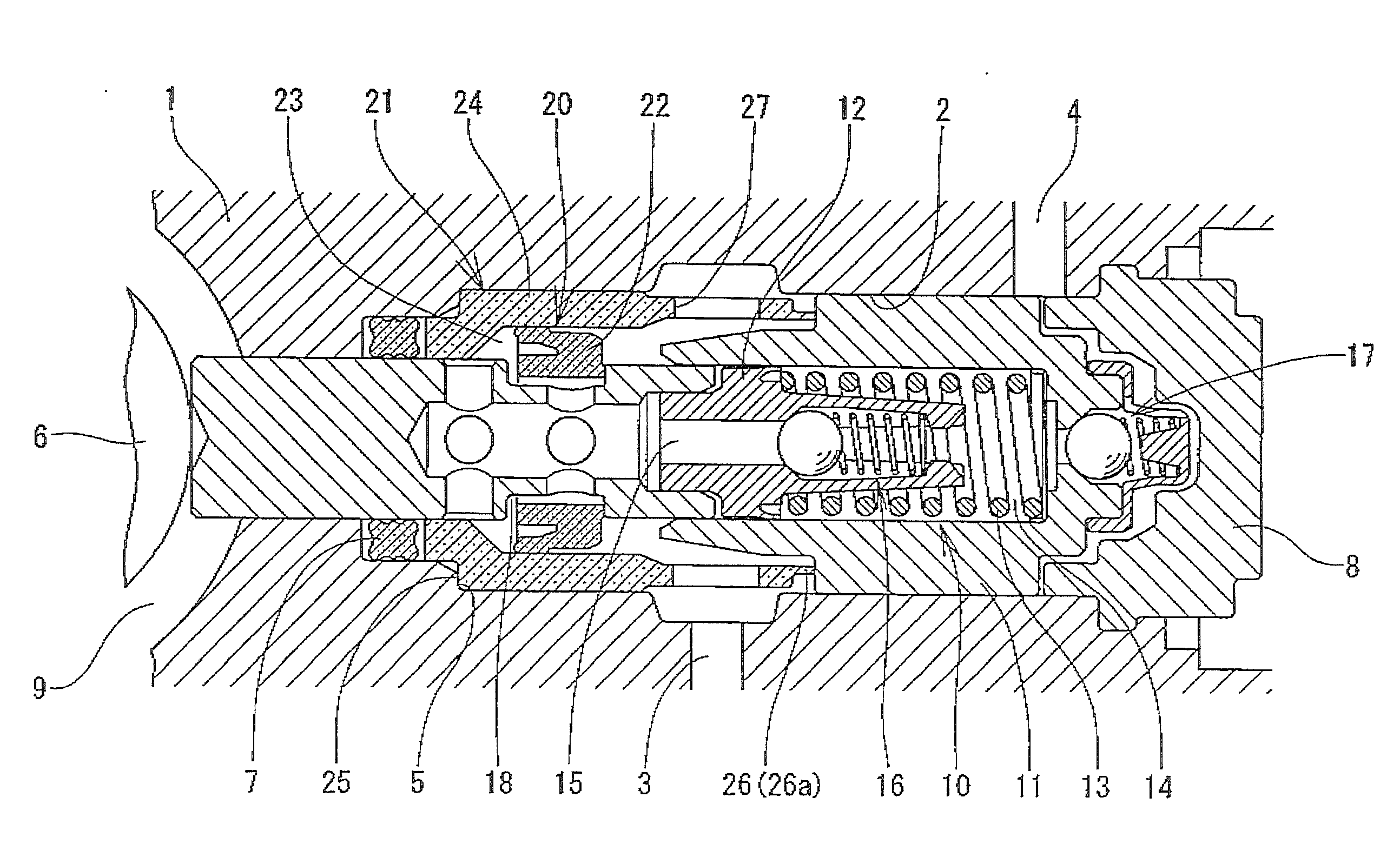
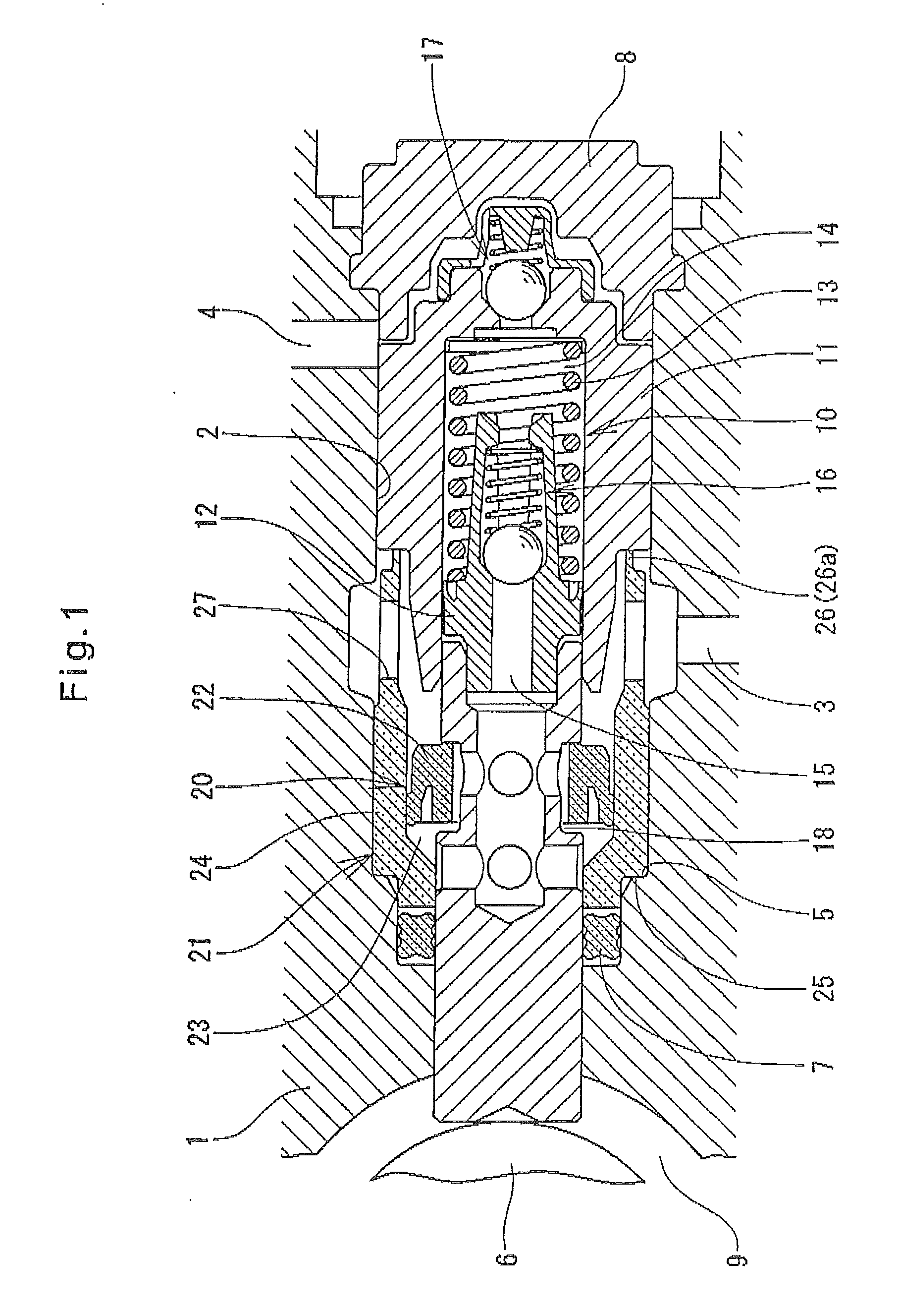
[0046]The piston pump assembly shown in FIG. 1 comprises a pump housing 1, a first pump 10, a second pump 20, an eccentric cam 6 for driving the first and second pumps, and an annular seal member 7, which is described below.

[0047]The pump housing 1 is formed with a piston hole 2, a fluid inlet port 3 communicating with the piston hole 2, and a discharge port 4 through which fluid drawn by the pumps are discharged. The first and second pumps 10 and 20 are mounted in the piston hole 2. The inlet of the piston hole 2 is liquid-tightly sealed by an end plug 8. The outlet of the first pump 10 communicates with the discharge port 4 through a chamber defined by the inner surface of the end plug 8.

[0048]The first pump10 includes a first cylinder member 11 mounted in the piston hole 2, a first piston 12 having one end thereof slidably inserted in the first cylinder member 11, and...


PUM


Abstract

A piston pump assembly includes a first pump having a first cylinder member inserted in a piston hole of a pump housing, and a first piston inserted in the first cylinder member, and a second pump having a second cylinder member inserted in the piston hole, and an annular second piston slidably fitted in an annular groove formed in the outer periphery of the first piston, and also axially slidably inserted in the second cylinder member. The first cylinder member axially presses the second cylinder member, thereby preventing the second cylinder member from being dropped out of the piston hole. The second cylinder member has an annular seal surface in contact with a shoulder surface formed on the inner periphery of the piston hole. Strain-absorbing protrusions are formed on the end of the second cylinder member in abutment with the first cylinder member. The protrusions are compressed when they are pressed by the first cylinder member.

Description

CROSS REFERENCE TO RELATED APPLICATIONS[0001]This application is based on and claims priority under 35 U.S.C. sctn. 119 with respect to Japanese Patent Application No. 2009-216994 filed on Sep. 18, 2009, the entire content of which is incorporated herein by reference.BACKGROUND OF THE INVENTION[0002]This invention relates to a piston pump assembly used in hydraulic devices such as hydraulic pressure control devices, hydraulic pressure boosters and high-pressure pumps for pressure accumulators, and particularly to a piston pump assembly having a self-suction function which can by itself pressurize fluid to be drawn into a pump chamber and feed it into the pump chamber under pressure.[0003]There is known a piston pump assembly of the type in which fluid (liquid) used as a pressure medium is pre-pressurized by a second pump, and re-pressurized by a first pump, and then discharged. A piston pump assembly of this type is disclosed e.g. in JP Patent Publication 2005-113880A (hereinafter r...

Claims


Application Information

Patent Timeline
IPC IPC(8): F04B53/14
CPCB60T8/4031F04B53/14F04B1/0408
Inventor SUMIMOTO, ATSUSHIHARADA, TOMOO
Owner ADVICS CO LTD
Why Eureka
Try Eureka