
Particulate filter regeneration during engine shutdown

a technology of particulate filter and engine shutdown, which is applied in the field of engines, can solve the problems of di engines being susceptible to generating soot, rich combustion pockets that generate soot, etc., and achieve the effect of facilitating the regeneration of particulate filter and reducing the impact of engine running emissions

Active Publication Date: 2011-03-31
FORD GLOBAL TECH LLC
View PDF3 Cites 34 Cited by
  • Summary
  • Abstract
  • Description
  • Claims
  • Application Information

AI Technical Summary

Benefits of technology

[0006]In this manner, at least some filter regeneration in a spark-ignited engine may be carried out while the engine is shutdown, thus reducing an impact on engine running emissions. Thus, in the example where filter regeneration also occurs during engine operation, less engine-running filter regeneration may be used.
[0007]In one specific example, an exhaust gas recirculation (EGR) system may be employed to facilitate regeneration of the particulate filter. After the engine is shutdown, an EGR valve may be opened and the vacuum pump turned on so that fresh air is drawn through the particulate filter and into the intake manifold via the EGR system. In this way, fresh air containing oxygen (e.g., O2) may be drawn through the particulate filter thus assisting in regeneration of the particulate filter. In another embodiment, positive valve overlap of at least one cylinder being present at the stopped position may be used instead of, or in addition to, the EGR system, to enable fresh airflow from the exhaust system to the intake system while the engine is at rest.

Problems solved by technology

As a consequence of diffuse flame propagation, fuel may not adequately mix with air prior to combustion resulting in pockets of rich combustion that generate soot.
Further, DI engines may be susceptible to generating soot during high load and / or high speed conditions when there is a lack of sufficient air and fuel mixing.

Method used


Image

  • Particulate filter regeneration during engine shutdown
  • Particulate filter regeneration during engine shutdown
  • Particulate filter regeneration during engine shutdown

Examples


Embodiment Construction

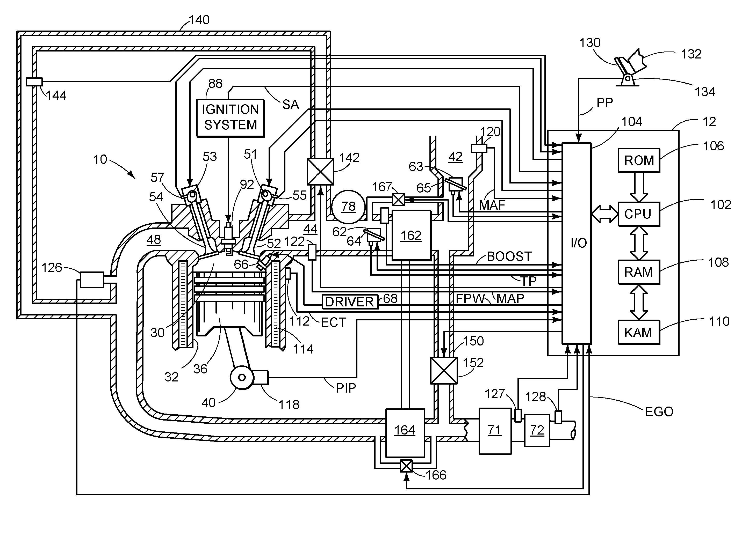
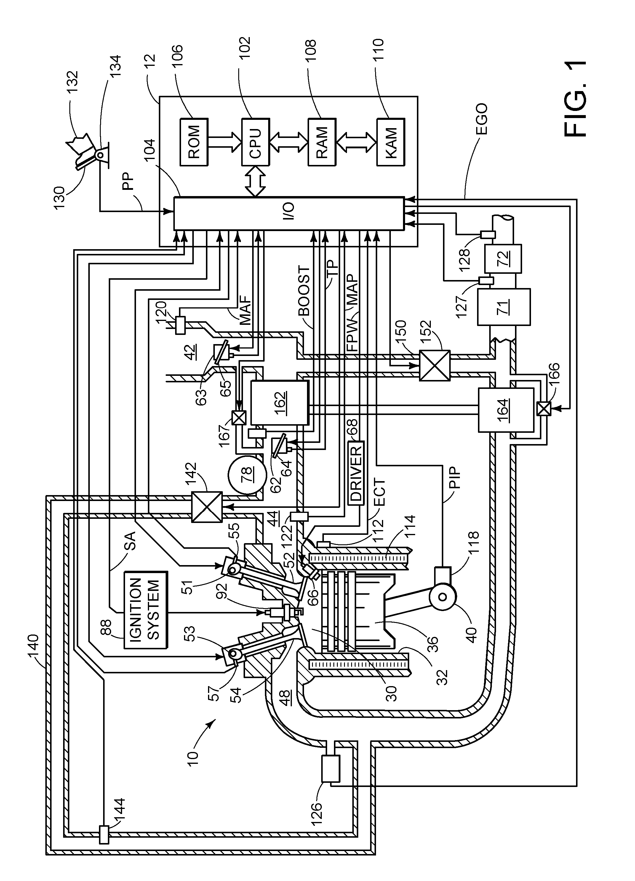
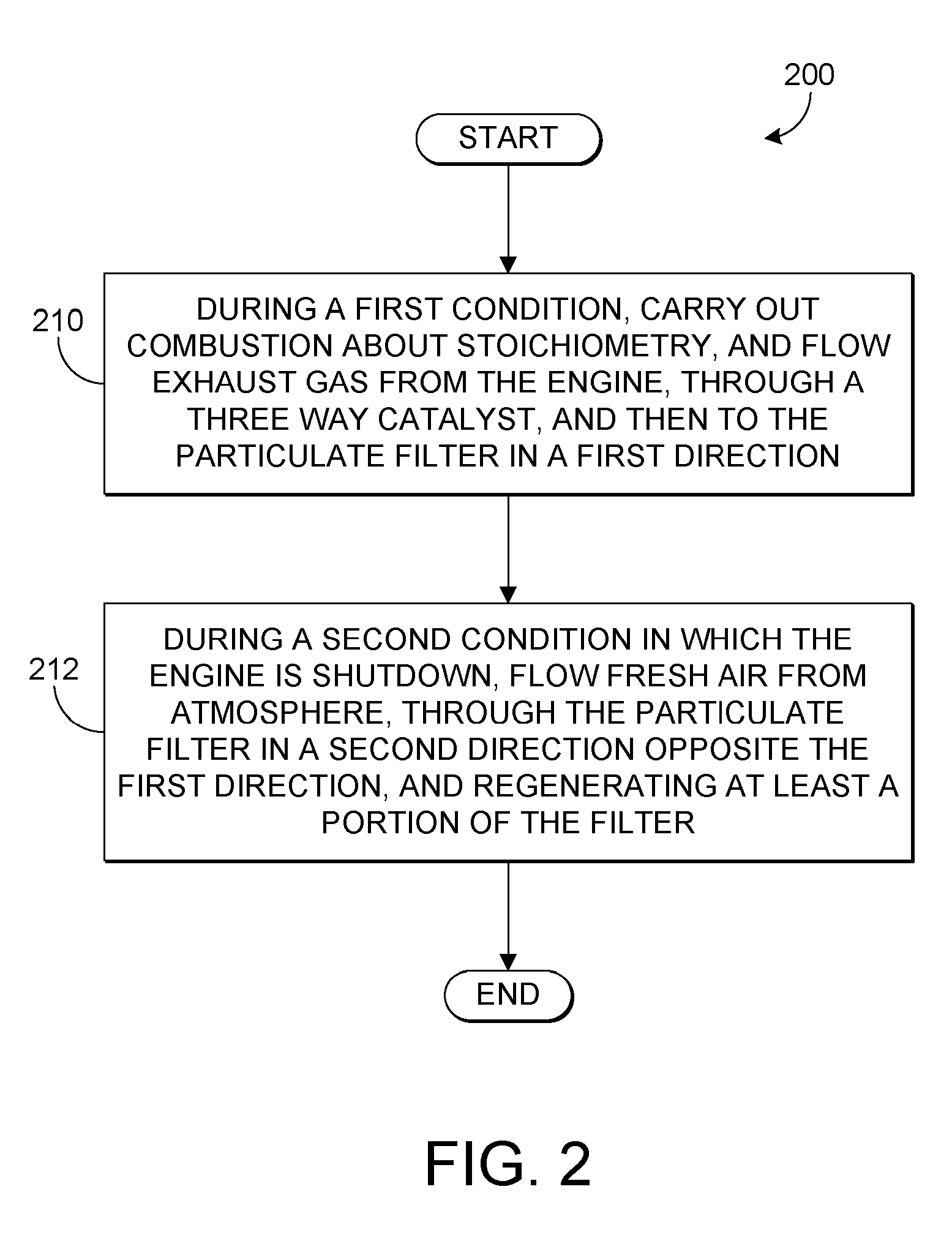
[0016]The following description relates to a method for regenerating a particulate filter in an engine, such as a direct injection gasoline engine. During a first operating condition of the engine, combustion in the engine may be carried out about stoichiometry and exhaust gas may flow from the engine in a first direction, through a three way catalyst, and then to a particulate filter where soot generated by the engine is collected. During a second operating condition in which the engine is shutdown, fresh air may flow through the exhaust system in a second direction which is opposite the first direction in order to assist in regeneration of the particulate filter. Fresh air flowing in the second direction may be drawn in through the tailpipe via a vacuum pump coupled to the intake manifold so that it flows through the particulate filter and then to the intake manifold. In some embodiments, an exhaust gas recirculation (EGR) system may be utilized to allow air to flow between the ex...


PUM


Abstract

Various systems and method are described for controlling an engine having an exhaust system which includes a particulate filter. One example method comprises, after shutting down the engine and spinning down the engine to rest, operating a vacuum pump to draw fresh air through the exhaust system to an intake system, and regenerating at least a portion of the particulate filter during the engine rest.

Description

CROSS REFERENCE TO RELATED APPLICATIONS[0001]The present application claims priority to U.S. Provisional Patent Application No. 61 / 246,933, filed Sep. 29, 2009, titled “Particulate Filter Regeneration During Engine Shutdown,” the entire contents of each of which are incorporated herein by reference.TECHNICAL FIELD[0002]The present application relates generally to an engine having an exhaust system which includes a particulate filter.BACKGROUND AND SUMMARY[0003]Direct injection (DI) engines may produce more soot than port fuel injected engines due to, for example, diffuse flame propagation. As a consequence of diffuse flame propagation, fuel may not adequately mix with air prior to combustion resulting in pockets of rich combustion that generate soot. Further, DI engines may be susceptible to generating soot during high load and / or high speed conditions when there is a lack of sufficient air and fuel mixing.[0004]The inventors herein have recognized various issues in applying particu...

Claims


Application Information

Patent Timeline
Patent Type & Authority Applications(United States)
IPC IPC(8): F02M25/06F01N3/023F01N3/035F02D43/00
CPCF01N3/30F02D41/0055F02D41/029F02D41/042F02D2200/0812F02M25/0707F01N13/009F01N3/023F01N3/0233F01N3/0238F01N3/101Y02T10/22F02M25/0709F02M26/05F02M26/06Y02A50/20Y02T10/12
Inventor BIDNER, DAVID KARLCUNNINGHAM, RALPH WAYNEHEPBURN, JEFFREY SCOTT
Owner FORD GLOBAL TECH LLC
Features
  • Generate Ideas
  • Intellectual Property
  • Life Sciences
  • Materials
  • Tech Scout
  • Unparalleled Data Quality
  • Higher Quality Content
  • 60% Fewer Hallucinations
Learn More