
Engine brake unit having combined oil passage

a brake unit and oil passage technology, applied in the direction of valve arrangement, machines/engines, output power, etc., can solve the problems of reducing engine life, complicated oil construction, and excessive amount of load applied to respective parts of engines, so as to reduce weight and manufacturing costs, simplify the structure of the oil passage, and facilitate manufacturing

Active Publication Date: 2011-03-31
HYUNDAI MOTOR CO LTD +1
View PDF40 Cites 39 Cited by
  • Summary
  • Abstract
  • Description
  • Claims
  • Application Information

AI Technical Summary

Benefits of technology

[0017]Various aspects of the present invention are directed to provide an engine brake unit having a combined oil passage, which can reduce weight and manufacturing cost due to a simplified configuration having combined oil passages and an actuator integrally provided inside an exhaust rocker arm.
[0029]According to exemplary embodiments of the present invention as set forth above, the oil passage structure is simplified since the oil passages are combined with each other, the rocker shaft and the exhaust rocker arm can be easily manufactured. Furthermore, weight and manufacturing cost can be reduced since the actuator is integrally provided inside the rocker arm.

Problems solved by technology

In engine braking, however, an excessive amount of load is applied to respective parts of an engine when a transmission is down-shifted.
This may cause drawbacks such as reduced engine lifetime.
Such a conventional art has a complicated construction of oil passages since the lubricating oil passage and the brake oil passage are separately formed in the rocker shaft and the rocker arm.
The problem of the conventional art is inefficiency.
However, such a conventional engine brake unit has problems such as an increase in weight and production cost due to an increase in the number of parts since the housing, inside of which the actuator of the engine brake is stored, is additionally provided.

Method used


Image

  • Engine brake unit having combined oil passage
  • Engine brake unit having combined oil passage
  • Engine brake unit having combined oil passage

Examples


Embodiment Construction

[0040]Reference will now be made in detail to various embodiments of the present invention(s), examples of which are illustrated in the accompanying drawings and described below. While the invention(s) will be described in conjunction with exemplary embodiments, it will be understood that present description is not intended to limit the invention(s) to those exemplary embodiments. On the contrary, the invention(s) is / are intended to cover not only the exemplary embodiments, but also various alternatives, modifications, equivalents and other embodiments, which may be included within the spirit and scope of the invention as defined by the appended claims.

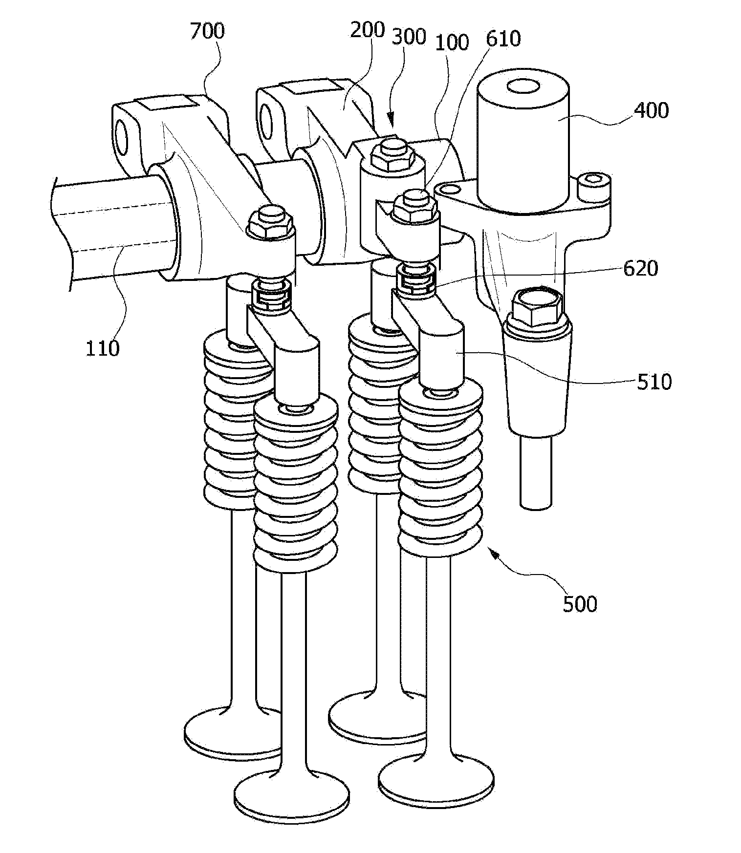
[0041]FIG. 2 is a perspective view illustrating an engine brake unit having a combined oil passage in accordance with an exemplary embodiment of the present invention, and FIGS. 3A and 3B are perspective views each illustrating important parts of the engine brake unit having a combined oil passage shown in FIG. 2.

[0042]The engine brak...


PUM


Abstract

An engine brake unit, may include a rocker shaft having an oil passage to open or close an exhaust valve when an engine braking is in operation, an exhaust rocker arm rotatable about the rocker shaft inserted into the exhaust rocker arm, wherein the exhaust rocker arm includes a supply oil passage communicating with the oil passage and the outside, and a recess connected to the supply oil passage and having an open lower portion, an actuator disposed in the recess of the exhaust rocker arm, wherein the actuator includes a piston that selectively moves downwards through the open lower portion of the recess by oil supplied from the supply oil passage to press the exhaust rocker arm while oil pressure in the oil passage has a predetermined pressure or more, and an oil control valve connected to the oil passage of the rocker shaft and controlling the oil pressure.

Description

CROSS REFERENCE TO RELATED APPLICATION[0001]The present application claims priority to Korean Patent Application Number 10-2009-0091084 filed on Sep. 25, 2009, the entire contents of which application is incorporated herein for all purposes by this reference.BACKGROUND OF THE INVENTION[0002]1. Field of the Invention[0003]The present invention relates to an engine brake unit having a combined oil passage, more particularly, to an engine brake unit having a combined oil passage, in which a single oil passage structure is produced by combining an engine brake oil passage and a lubricating oil passage together in such a manner that an engine brake can be operated by the single oil passage structure.[0004]2. Description of Related Art[0005]Engine braking generally refers to the act of slowing down a vehicle by down-shifting to a lower transmission gear. In engine braking, however, an excessive amount of load is applied to respective parts of an engine when a transmission is down-shifted....

Claims


Application Information

Patent Timeline
IPC IPC(8): F02D13/04
CPCF01L1/181F01L2810/02F01L13/06F01L1/267F01L1/18F02D13/04
Inventor YOON, SEOCK JOONGKIM, KYUNG MO
Owner HYUNDAI MOTOR CO LTD
Features
  • Generate Ideas
  • Intellectual Property
  • Life Sciences
  • Materials
  • Tech Scout
  • Unparalleled Data Quality
  • Higher Quality Content
  • 60% Fewer Hallucinations
Learn More