Light-emitting diode and method for manufacturing the same

a technology of light-emitting diodes and manufacturing methods, which is applied in the direction of semiconductor/solid-state device manufacturing, electrical apparatus, semiconductor devices, etc., can solve the problems of increasing the operation voltage vf, affecting the lifetime and operation stability, and non-uniform current density, so as to improve the stability of wiring bonding and light extraction efficiency, avoid current congestion effect, and increase the light-emitting efficiency of led

Inactive Publication Date: 2011-03-31
CHI MEI LIGHTING TECH
View PDF5 Cites 43 Cited by
  • Summary
  • Abstract
  • Description
  • Claims
  • Application Information

AI Technical Summary

Benefits of technology

[0008]One objective of the present invention is to provide an LED having flat surface regions on which a p-type electrode and an n-type electrode are disposed and rough surface regions for improving the stability of the wiring bonding and the light extraction efficiency.
[0009]Another objective of the present invention is to provide an LED having a p-type semiconductor layer with at least flat surface region in which p+ doped semiconductors are removed and a transparent conductive layer such that in operation, a current flow vertically from the transparent conductive layer to the at least flat surface region of the p-type semiconductor layer is blocked, thereby, avoiding the current congestion effect

Problems solved by technology

This will reduce the current spreading ability of the transparent conductive layer 212 and thus give rise to increase of the operation voltage Vf and non-uniformity of the current density, thereby, affecting the lifetime and the operation stability of the LED.
The presence of the voids 218, which may contain air, chemical remains and/or photoresists, degrades the reliability of the LED.
In addition, because of the rough surface profile 224 of the p-type electrod

Method used


Image

  • Light-emitting diode and method for manufacturing the same
  • Light-emitting diode and method for manufacturing the same
  • Light-emitting diode and method for manufacturing the same

Examples


Embodiment Construction

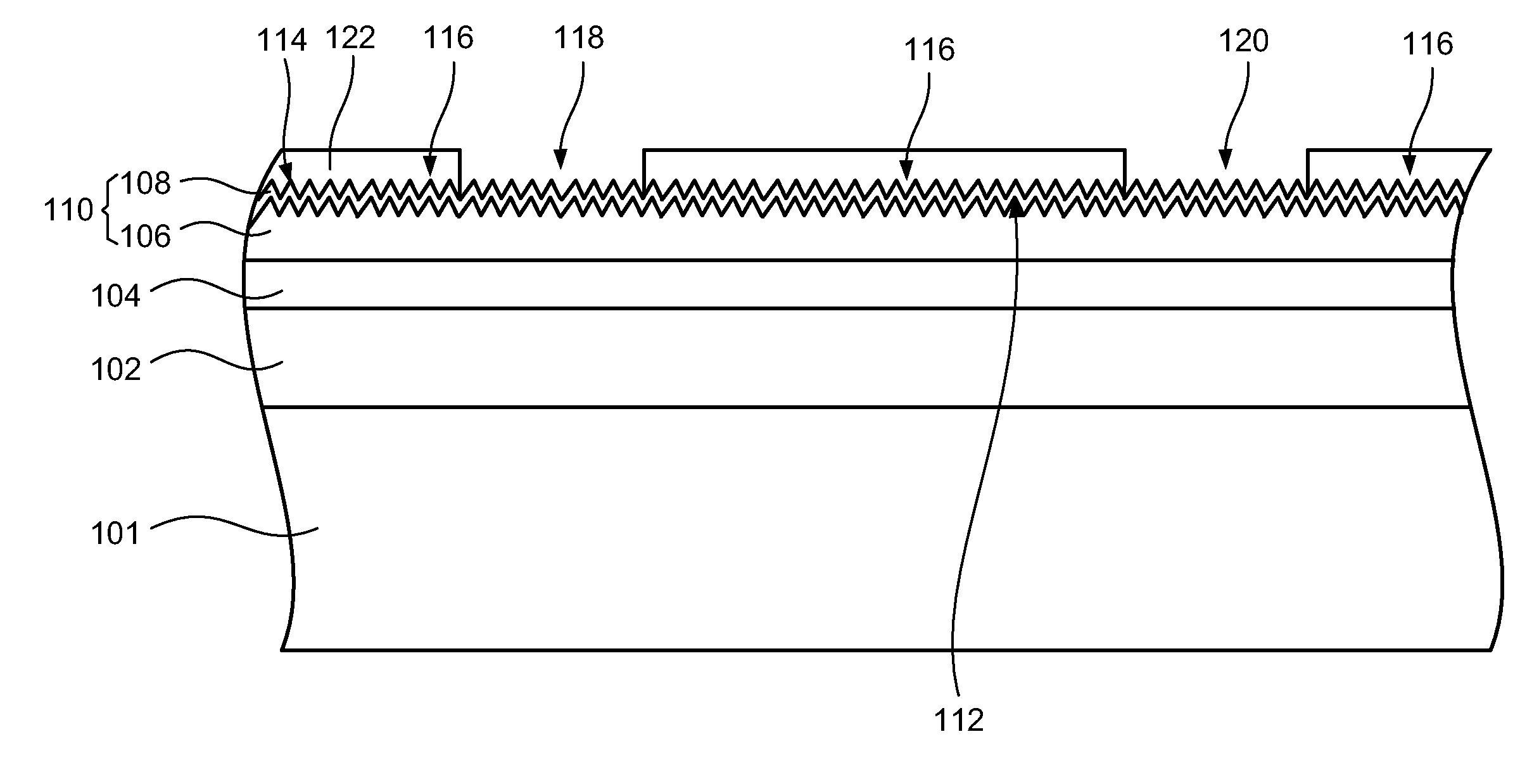
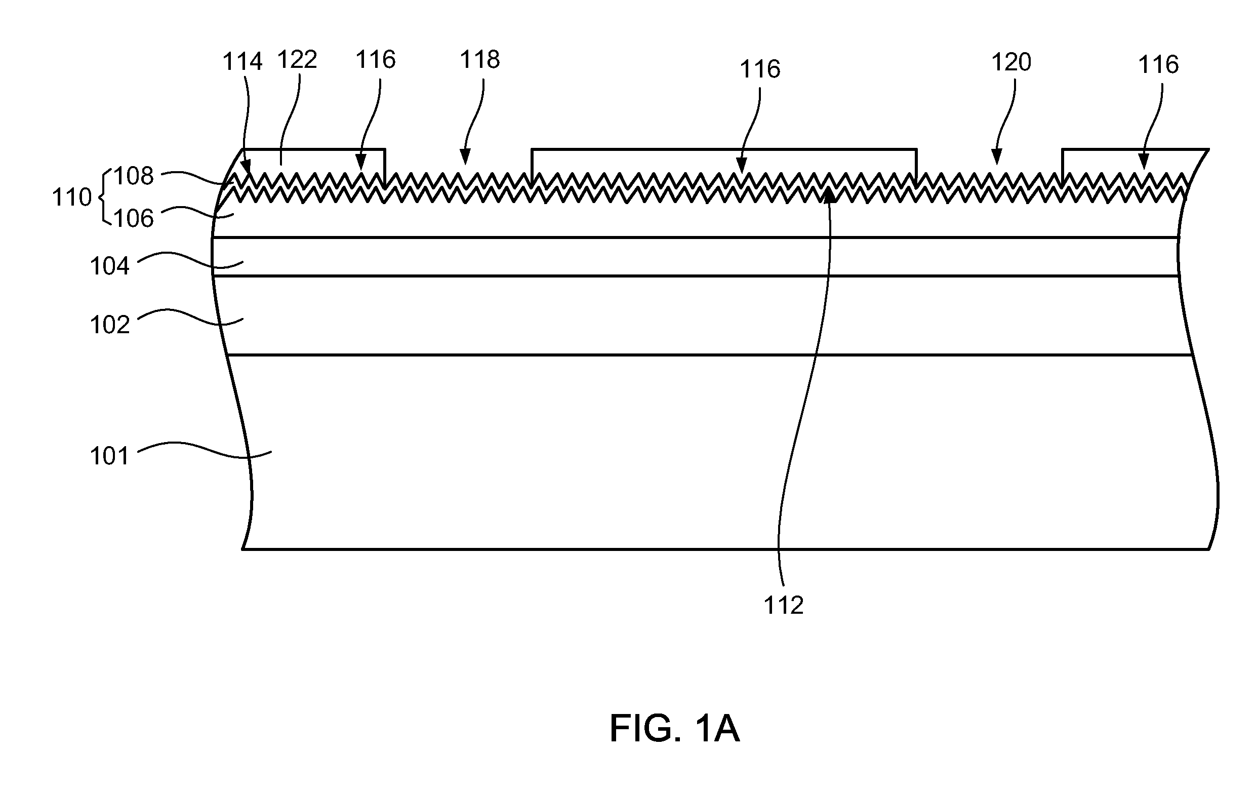
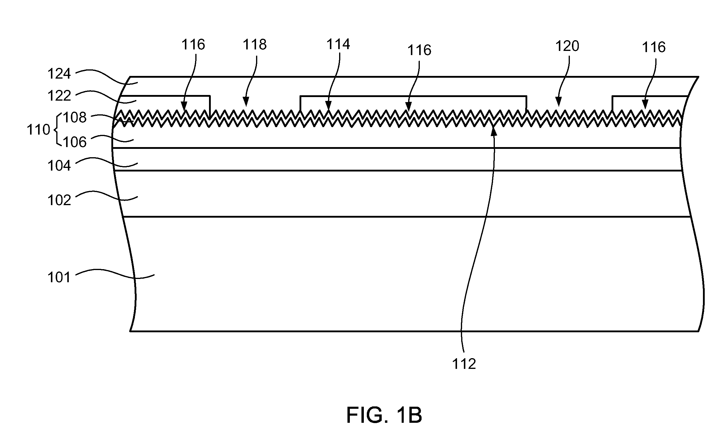
[0044]The present invention will now be described more fully hereinafter with reference to the accompanying drawings, in which exemplary embodiments of the invention are shown. This invention may, however, be embodied in many different forms and should not be construed as limited to the embodiments set forth herein. Rather, these embodiments are provided so that this disclosure will be thorough and complete, and will fully convey the scope of the invention to those skilled in the art. Like reference numerals refer to like elements throughout.

[0045]Example embodiments are described herein with reference to cross-sectional illustrations that are schematic illustrations of idealized embodiments (and intermediate structures) of example embodiments. As such, variations from the shapes of the illustrations as a result, for example, of manufacturing techniques and / or tolerances, are to be expected. Thus, example embodiments should not be construed as limited to the shapes of regions illust...


PUM


Abstract

In one aspect of the invention, an LED includes a substrate, an n-type semiconductor layer, a light emitting layer, a p-type semiconductor layer and a transparent conductive layer sequentially stacked on the substrate, and p-type and n-type electrodes. The p-type semiconductor layer has a rough surface region and at least one flat surface region. The transparent conductive layer has a rough surface region and a flat surface region corresponding to the rough surface region and the at least one flat surface region of the p-type semiconductor layer, respectively. The p-type electrode is disposed on the flat surface region of the transparent conductive layer. The n-type electrode is electrically couple to the n-type semiconductor layer.

Description

CROSS-REFERENCE TO RELATED PATENT APPLICATION[0001]Some references, which may include patents, patent applications and various publications, are cited and discussed in the description of this invention. The citation and / or discussion of such references is provided merely to clarify the description of the present invention and is not an admission that any such reference is “prior art” to the invention described herein. All references cited and discussed in this specification are incorporated herein by reference in their entireties and to the same extent as if each reference were individually incorporated by reference.FIELD OF THE INVENTION[0002]The present invention relates generally to a light emitting diode (LED), and more particular to an LED that utilizes a structure of flat surface regions formed under n-type and p-type electrodes and rough surface regions formed outside the n-type and p-type electrodes to enhance the wiring boding stability and improve the light extraction effi...

Claims


Application Information

Patent Timeline
IPC IPC(8): H01L33/10H01L33/58H01L33/44H01L33/00
CPCH01L33/22H01L33/44H01L33/42
Inventor CHU, CHANG HSINLU, CHI MENGCHANG, YU JUYU, KUO HUI
Owner CHI MEI LIGHTING TECH
Why Eureka
Try Eureka