Coil spring for automobile suspension and method of manufacturing the same

a technology for automobile suspensions and coil springs, which is applied in the direction of manufacturing tools, furnaces, heat treatment equipment, etc., can solve the problems of inconvenient sequence of steps, short service life of coil springs, and rapid loss of essential spring properties of coil springs, so as to achieve effective improvement of sag resistance and durability of coil springs for automobile suspensions

Active Publication Date: 2011-03-31
CHUO SPRING
View PDF61 Cites 12 Cited by
  • Summary
  • Abstract
  • Description
  • Claims
  • Application Information

AI Technical Summary

Benefits of technology

[0029]The new and useful coil spring exhibiting this property is very capable of handling the large tensile stress that is mainly applied along the direction of 135-315 degrees during use, even if the original surface is worn away; therefore, the sag resistance and durability of the coil spring for an automobile suspension are effectively improved.

Problems solved by technology

If this relationship changes or deteriorates quickly, the coil spring will quickly lose essential spring properties.
A coil spring is also subject to breakage due to repeated application of cyclical stresses.
As a result of extensive and intensive studies, the inventors have discovered that this sequence of steps is disadvantageous for the following reason.
However, the inventors have found that this desirable oriented residual stress generated by the hot setting step is weakened when the warm shot peening step is performed after the hot setting step.
However, even if the ratio of the residual stress oriented along the direction of 135-315 degrees divided by the residual stress oriented along the direction of 45-225 degrees is relatively high, sometimes a suitable sag resistance or durability still cannot be obtained.

Method used


Image

  • Coil spring for automobile suspension and method of manufacturing the same
  • Coil spring for automobile suspension and method of manufacturing the same
  • Coil spring for automobile suspension and method of manufacturing the same

Examples


examples

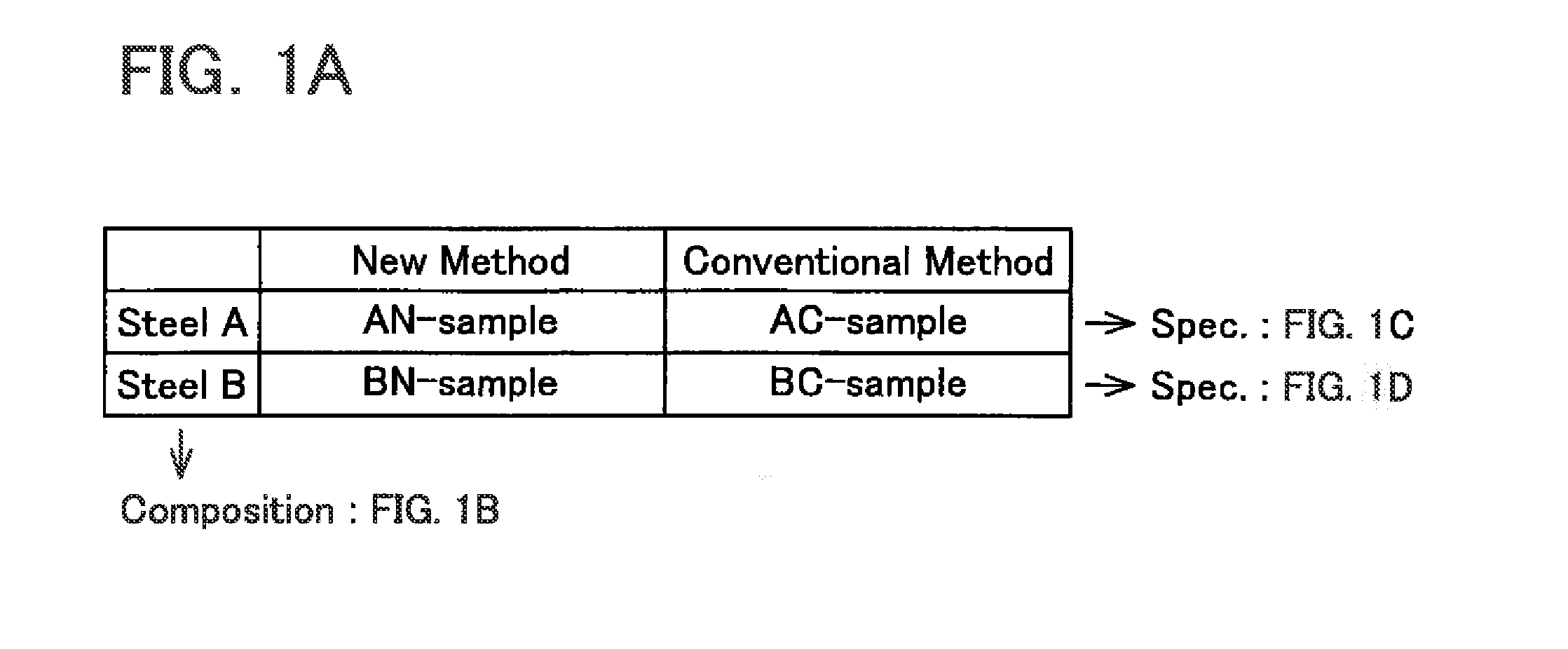
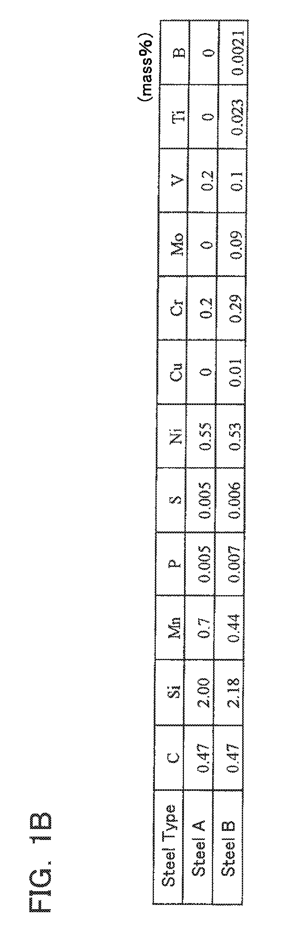
[0084]Two types of steel wire A and B having the different compositions shown in FIG. 1B were used for testing purposes. Two types of coil springs for an automobile suspension were manufactured using each of the respective steel wires. One set of coil springs (AN-sample and BN-sample) was manufactured according to the new method disclosed herein and the other set of coil springs (AC-sample and BC-sample) was manufactured using the above-described conventional method. FIG. 1A provides a convenient reference for understanding the composition and manufacturing method of the four coil springs. Further, the specifications and properties of the coil springs of the AN-sample and AC-sample are shown in FIG. 1C, and the specifications and properties of the coil springs of the BN-sample and BC-sample are shown in FIG. 1D.

[0085]Steel wire A has the composition shown in FIG. 1B. The remainder of the aforementioned composition is iron (Fe), and incidental elements and / or unavoidable impurities. ...


PUM

PropertyMeasurementUnit
temperatureaaaaaaaaaa

Abstract

A manufacturing method of a coil spring for an automobile suspension includes forming a material into a coil shape; performing a heat treatment step on the material; performing a warm shot peening step on the material, and performing a hot setting step on the material. By performing the warm shot peening step prior to the hot setting step, a stronger compressive residual stress is imparted in a direction along which a large tensile stress acts during actual use of the coil spring, thereby improving sag resistance and durability of the coil spring. A coil spring is also manufactured according to this method.

Description

CROSS-REFERENCE TO RELATED APPLICATION[0001]The present application claims priority to Japanese Patent Application Nos. 2009-225422, 2009-225423 and 2009-225424, all of which were filed on Sep. 29, 2009, and to Japanese Patent Application No. 2010-009072 filed on Jan. 19, 2010, the contents of all of which are hereby incorporated by reference into the present application.TECHNICAL FIELD[0002]The present application relates to a coil spring for an automobile suspension. The present application also relates to a method of manufacturing the same.DESCRIPTION OF THE RELATED ART[0003]A coil spring for an automobile suspension is typically made by shaping a steel wire or rod (hereinafter collectively “steel wire”). A conventional method for manufacturing such a coil spring is disclosed at page 508 of the textbook SPRING, 4th edition edited by the Japan Society of Spring Engineers and includes the following steps:[0004]1) The steel wire is formed into a coil shape;[0005]2) the coil-shaped s...

Claims


Application Information

Patent Timeline
Patent Type & Authority Applications(United States)
IPC IPC(8): F16F1/06C21D9/02B60G11/14B23P15/00B23P17/00
CPCC22C38/04C22C38/34C22C38/42C22C38/44Y10T29/49611C22C38/54Y10T29/49615Y10T29/479C22C38/50
Inventor NAKANO, TOMOHIROSAKAKIBARA, TAKAYUKIKUNO, TAKANORIMIMURA, SHINGOWAKITA, MASAMI
Owner CHUO SPRING
Why Eureka
Try Eureka