
Calibration system for multi-printhead ink systems

a multi-printhead ink and calibration system technology, applied in printing, other printing apparatus, etc., can solve the problems of system requiring extremely high cost encoders to provide resolution, system is also very susceptible to errors produced, and subject to errors

Active Publication Date: 2011-03-31
EASTMAN KODAK CO
View PDF3 Cites 33 Cited by
  • Summary
  • Abstract
  • Description
  • Claims
  • Application Information

AI Technical Summary

Benefits of technology

[0009]The present invention has the advantage of calibrating multi-printhead systems by modifying the encoder pulse train.

Problems solved by technology

Such a system requires extremely high cost encoders to provide the resolution needed for the registration demands of a printer system.
It also is subject to errors associated with slip or coupling between the motor and the motion of the paper through the print zone.
This system is also very susceptible to errors produced by variations in motor speed such as wow and flutter.

Method used


Image

  • Calibration system for multi-printhead ink systems
  • Calibration system for multi-printhead ink systems
  • Calibration system for multi-printhead ink systems

Examples


Embodiment Construction

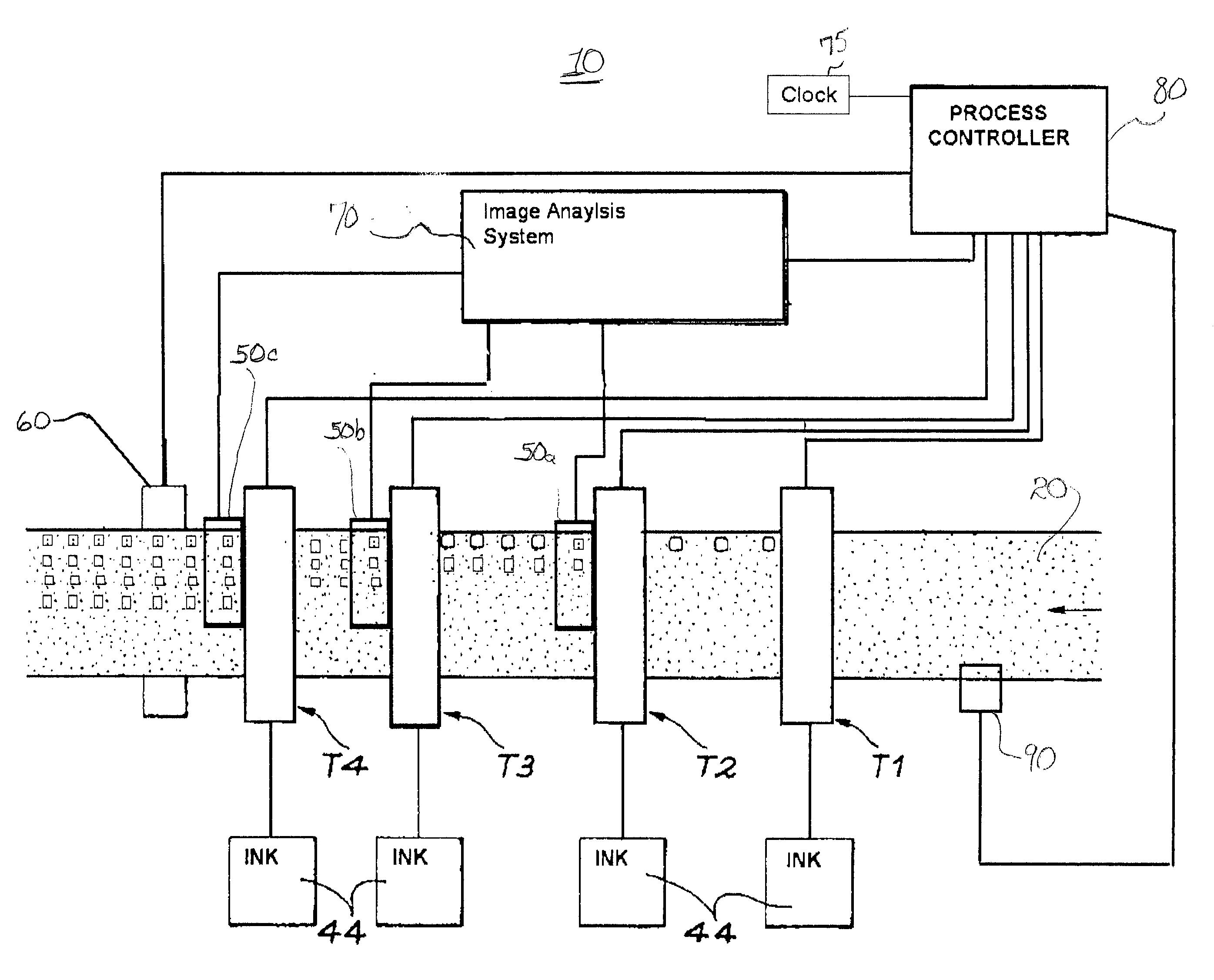
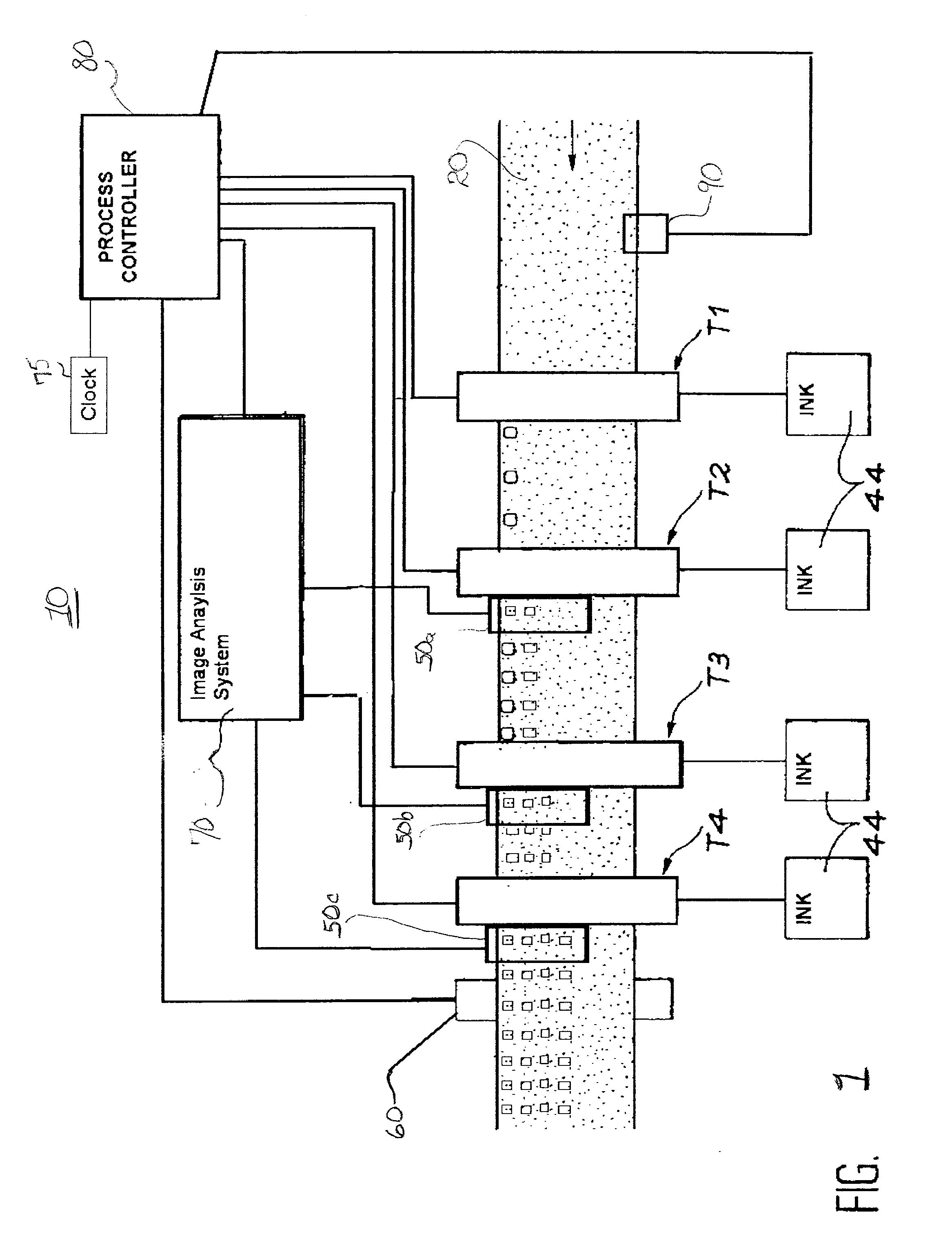
[0020]Turning now to FIG. 1, there is shown a block diagram of the printing system 10 of the present invention. The printing system 10 includes a transport for transporting the print media 20 through various stages of the printing process. Four printheads (T1, T2, T3 and T4) span over the print media 20 each for dispensing ink of a different color on the print media 20 as the media 20 moves relative to the printheads T1-T4. Four ink holding receptacles 44, each of a different color, are respectively attached to each printhead T1-T4 for supplying ink thereto. Three image capture devices 50a, 50b and 50c are respectively disposed immediately downstream (i.e, in close proximity) of each of the last three printhead T2-T4 but not after the first printhead T1. Each image capture device 50a, 50b and 50c includes a digital camera and a light source both of which will be described in detail hereinbelow. Typically the light sources are strobe lights for producing short bright flashes of light...


PUM


Abstract

A method for calibrating a multi-printhead printing system, the method includes the steps of employing an encoder to track movement of a media through the printing system; providing a first printhead that prints a first image plane that includes a first test mark at a first defined location on the media as the media moves relative to the first printhead; providing a second printhead that prints a second image plane that includes a second test mark at a second defined location on the media as the media moves relative to the second printhead; employing a first image capture device that captures an image that includes both the first and second test marks; determining an error factor based on the placement of the second mark relative to the first mark in the captured image; and creating a frequency-shifted pulse train of the encoder in which the frequency shift is based on the error factor; wherein the first printhead prints the first image plane in response to output of the encoder and the second printhead prints the second image plane in response to the frequency-shifted pulse train of the encoder.

Description

CROSS REFERENCE TO RELATED APPLICATIONS[0001]Reference is made to commonly assigned U.S. patent application Ser. No.______ (Docket 95646) filed Sep. 29, 2009 by John Saettel, entitled “Exposure Averaging”, commonly assigned U.S. patent application Ser. No.______ (Docket 95644) filed Sep. 29, 2009 by John Saettel, entitled “Automated Time of Flight Speed Compensation”, and commonly assigned U.S. patent application Ser. No.______ (Docket 95645) filed Sep. 29, 2009 by John Saettel, entitled “Color to Color Registration Target”′ the disclosures of which are herein incorporated by reference.FIELD OF THE INVENTION[0002]The present invention generally relates to inkjet printing systems and, more particularly, to such inkjet systems that correct for printing deviations by using image capture devices to facilitate correction.BACKGROUND OF THE INVENTION[0003]Synchronizing printheads in order to correct for printing inaccuracies is a necessity in most printing systems since mechanical systems ...

Claims


Application Information

Patent Timeline
IPC IPC(8): B41J29/393
CPCB41J29/393B41J2/175
Inventor SAETTEL, JOHN J.MADER, RODNEY G.ALLRED, DONALD R.
Owner EASTMAN KODAK CO
Learn More