Method for correcting measurement error and electronic component characteristic measurement apparatus

a technology of electronic components and measurement equipment, applied in the direction of speed/acceleration/shock measurement, resistance/reactance/impedence, instruments, etc., can solve the problem of error in fixture, difficult identification of the true physical value of a standard device other than coaxial types, and practicability of producing a standard device for non-coaxial electronic components

Inactive Publication Date: 2005-11-01
MURATA MFG CO LTD
View PDF16 Cites 15 Cited by
  • Summary
  • Abstract
  • Description
  • Claims
  • Application Information

AI Technical Summary

Benefits of technology

[0021]The linear simultaneous equation is easily and automatically expressed using a computer algorithm. The correction method corresponding to a measurement system having any number of ports is provided by solving the linear simultaneous equation using a typical method such as the LU decomposition. This method is versatile enough to be applied to a measurement system without regard to the number of ports in use. If the speed of correction process is important, the linear simultaneous equation may be algebraically solved beforehand, and a correction calculation may be performed using the equation.
[0029]If the above-referenced improvements in the application conditions of the current or voltage are added to the error correction method of the present invention, the characteristics of the electronic component incorporated in the circuit forming the fixture are apparently considered as those of the electronic component under test. As a result, variations in the electrical characteristics of the active electronic component under test are prevented from changing.
[0031]Unlike the AC characteristics, the value of one of the DC voltage and the DC current applied to the active electronic component under test through the production test fixture is relatively easily equalized with the value of one of the DC voltage and the DC current applied to the active electronic component under test through the standard test fixture.
[0037]As discussed above, if the electrical characteristics of the correction data acquisition specimen are measured in a state that at least one of the ports of the correction data acquisition specimen prevents a DC current from flowing therethrough, the relationship of the DC voltage or the DC current of the fixture circuit remains unchanged. In this way, the calibration accuracy is free from degradation. For example, a capacitor may be connected to the port of the correction data acquisition specimen to allow an AC current only to flow therethrough with a DC signal blocked.

Problems solved by technology

It is practically impossible to produce a standard device for these non-coaxial electronic components.
This is because the identification of the true physical value of a standard device other than coaxial types is extremely difficult.
There is a possibility that an error takes place in the fixture.
A conventional art for calibrating a non-coaxial electronic component during a particular measurement does not provide necessarily a high calibration accuracy.
However, a non-coaxial electronic component is not directly connected to the coaxial face (a calibration plane).
Each fixture has its own characteristics, and it is difficult to make uniform characteristics among a plurality of fixtures.
When characteristics of the non-coaxial electronic component are measured through the fixture, an error unique to each fixture naturally occurs.
This creates variations in measurement results, thereby leading to a degradation in calibration accuracy.
Making uniform characteristics among a plurality of fixtures in a non-coaxial electronic component having three ports (such as a duplexer) is even more difficult, and fixtures are not practicable.
Electronic components working on a balanced signal in high frequency regions rather than on an unbalanced signal are currently increasing in number.
For example, a filter having balanced input and output is a two-port device, but practically corresponds to an unbalanced device having four ports.

Method used


Image

  • Method for correcting measurement error and electronic component characteristic measurement apparatus
  • Method for correcting measurement error and electronic component characteristic measurement apparatus
  • Method for correcting measurement error and electronic component characteristic measurement apparatus

Examples


Embodiment Construction

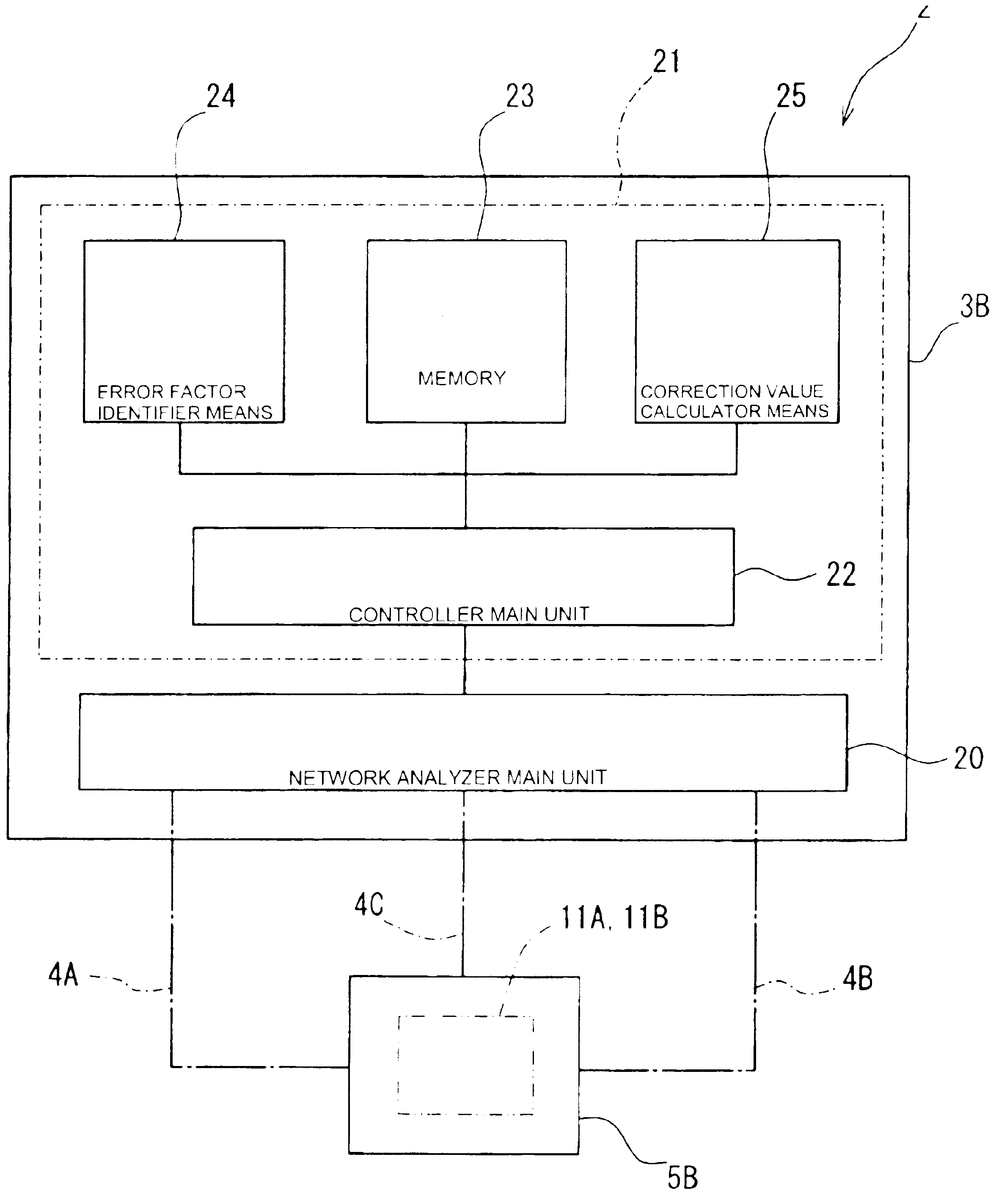
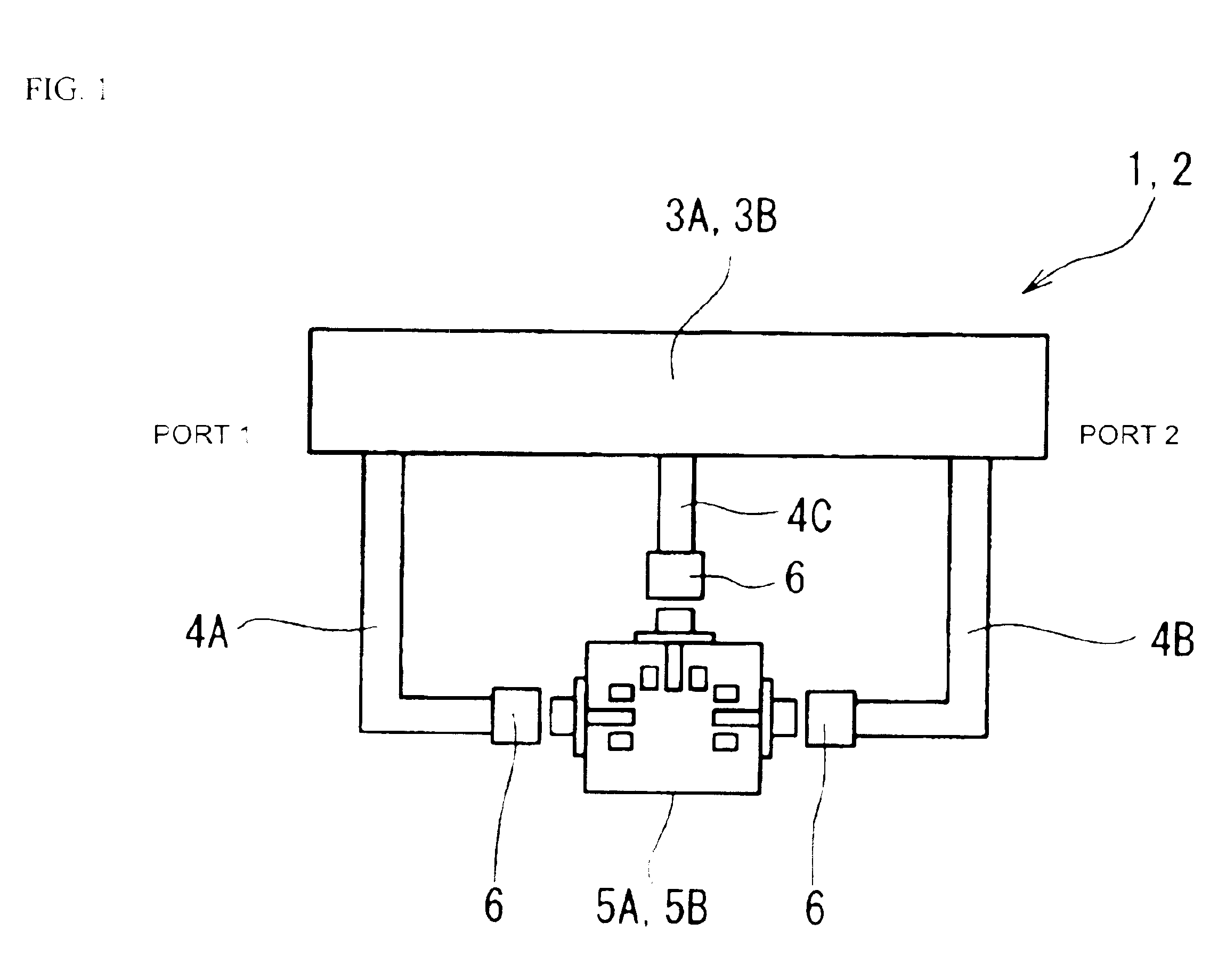
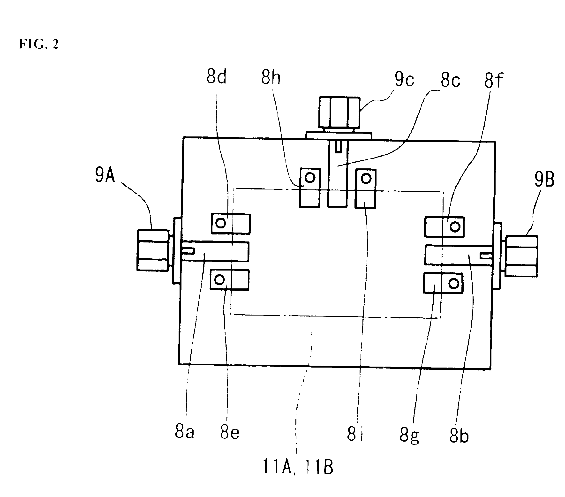
[0072]One embodiment of the present invention is discussed below. In the present embodiment, a surface mounted SAW filter is handled as an electronic component under test, and a measurement apparatus containing a network analyzer measures electrical characteristics of the surface mounted SAW filter. The present invention is implemented in a method of the test instrument for correcting an error in a measurement value thereof and an electrical characteristic measurement apparatus that adopts the correction method. The present invention is applicable to the correction method for correcting measurement results obtained from a device having at least two ports, and three ports in particular. The following discussion of the present invention focuses on a correction method for three-port measurement results, and an electrical characteristic measurement apparatus that adopts that correction method. However, the present invention is equally applicable to a correction method for four-port meas...


PUM


Abstract

A high-precision, multi-port compatible, relative correction method and apparatus for correcting measurement errors covering an increase in the number of ports of a non-coaxial electronic component, in which a relative correction adapter 31 is provided that is formed of a two-port network connected to each port of a production test fixture 5B adjacent to a measurement apparatus. The relative correction adapter has a characteristic that modifies the electrical characteristics generated by the production test fixture 5B having an electronic component under test mounted thereon into electrical characteristics generated by a standard test fixture 5A having the electronic component under test mounted thereon. An error factor of the relative correction adapter 31 is identified from a standard test fixture measurement value and a production test fixture measurement value of a correction data acquisition specimen 11B. A production test fixture measurement value of the electronic component under test 11A is corrected with the error factor of the relative correction adapter 31 to thereby obtain the standard test fixture measurement value of the electronic component under test 11A which is assumed to be obtained when the electronic component under test 11A.

Description

CROSS-REFERENCE TO RELATED APPLICATIONS[0001]This is a Continuation-In-Part of U.S. patent application Ser. No. 10 / 440,068, filed May 15, 2003, now U.S. Pat. No. 6,838,885, in the name of Gaku KAMITANI, entitled METHOD OF CORRECTING MEASUREMENT ERROR AND ELECTRONIC COMPONENT CHARACTERISTIC MEASUREMENT APPARATUS.BACKGROUND OF THE INVENTION[0002]1. Field of the Invention[0003]The present invention relates to a method of correcting a measurement error in which when electrical characteristics of an electronic component under test having a plurality of ports are measured using a test instrument with the electronic component under test mounted on a production test fixture, a production test fixture measurement value of the electronic component under test using the production test fixture is corrected to electrical characteristics that are assumed to be obtained when one of the test instrument and another test instrument considered equivalent to the test instrument in measurement performan...

Claims


Application Information

Patent Timeline
Patent Type & Authority Patents(United States)
IPC IPC(8): G01R27/00G01R27/28
CPCG01R27/28
Inventor KAMITANI, GAKU
Owner MURATA MFG CO LTD
Why Eureka
Try Eureka