Eureka AIR delivers breakthrough ideas for toughest innovation challenges, trusted by R&D personnel around the world.

Method for controlling peel position in a printer

a technology of peeling position and printer, which is applied in the direction of measuring devices, printing, instruments, etc., can solve the problems of creases or wrinkles in the dye transfer area, unused dye transfer area creases or wrinkles, web vulnerable to longitudinal stretching, etc., to reduce the incidence of machine jams, improve performance, and reduce the effect of printer defects

Inactive Publication Date: 2011-03-31
EASTMAN KODAK CO
View PDF9 Cites 8 Cited by
  • Summary
  • Abstract
  • Description
  • Claims
  • Application Information

AI Technical Summary

Benefits of technology

[0019]The present invention enables the design of improved thermal printers which provide improved performance in providing less printer defects and decreased incidence of machine jams. Furthermore the printer better accommodates for changing environmental conditions which change the peel force and better tolerates variations in manufacturing of the media which affect the tension requirements.

Problems solved by technology

Since, the dye transfer area in the color section is heated by the resistive elements the web is weakened, making the web vulnerable to being longitudinally stretched if too much tension is applied.
Consequently, too much longitudinal tension will stretch the donor web in the dye transfer area which in turn causes some creases or wrinkles to develop in the dye transfer area.
This indicates that too much tension on the dye donor web will result in creases or wrinkles being created in an unused dye transfer area and line artifacts being printed on the dye receiver medium during the dye transfer process.
More significantly, as each color section is drawn over the selectively heated resistive elements too little tension will cause the web to be slack.
Decreasing the tension further will cause more slackness in the web.
This will result in improper peeling or delamination of the dye donor web from the receiver web.
Improper peeling ranges from the peel position of the web shifting from the desired location at the peel bar to the extreme of not delaminating at all and causing a printer jam.
When the peel location of the dye donor web is not at its desired location there is a high probability for defects to occur in the printed image.
These defects include spot defects, creases, sticking defects and streaks.
Many of these defects are due to the fact that the donor web will selectively stick to the receiver web at specific locations if there is not enough web tension to maintain the peel location.
Spot defects are regions of low and high print density caused by micro folds in the donor sheet due to too little tension in the donor web.
Sticking defects are due to the detachment of the dye layer in a thermal donor from the PET (polyethylene terephthalate) support and transfer of the dye layer to the receiver during the peel process following printing.
This is a serious and unacceptable problem for the customer because it results in high density dye specs being scattered across the face of the receiver.
When this occurs the quality of the print can be adversely affected and in severe cases the webs stay laminated together and cause the printer to jam.
If the force applied to the web is too large then the webs may deform and introduce printing artifacts.
Furthermore changing environmental conditions such as ambient temperature and humidity can also cause the binding forces to change for a given set of donor and receiver webs.
None of the prior art can ensure that the location of the peel location is correct and that the thermal printer is working at its designed print resolution.

Method used

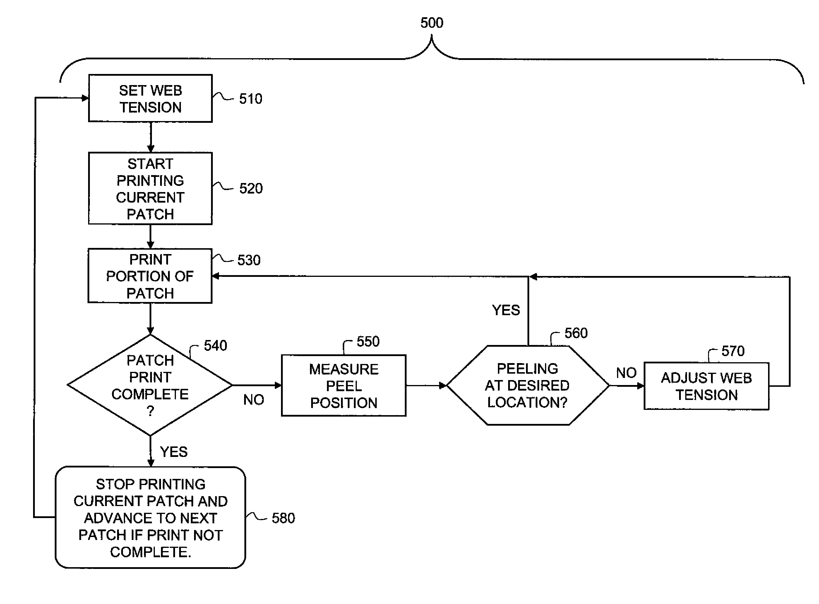
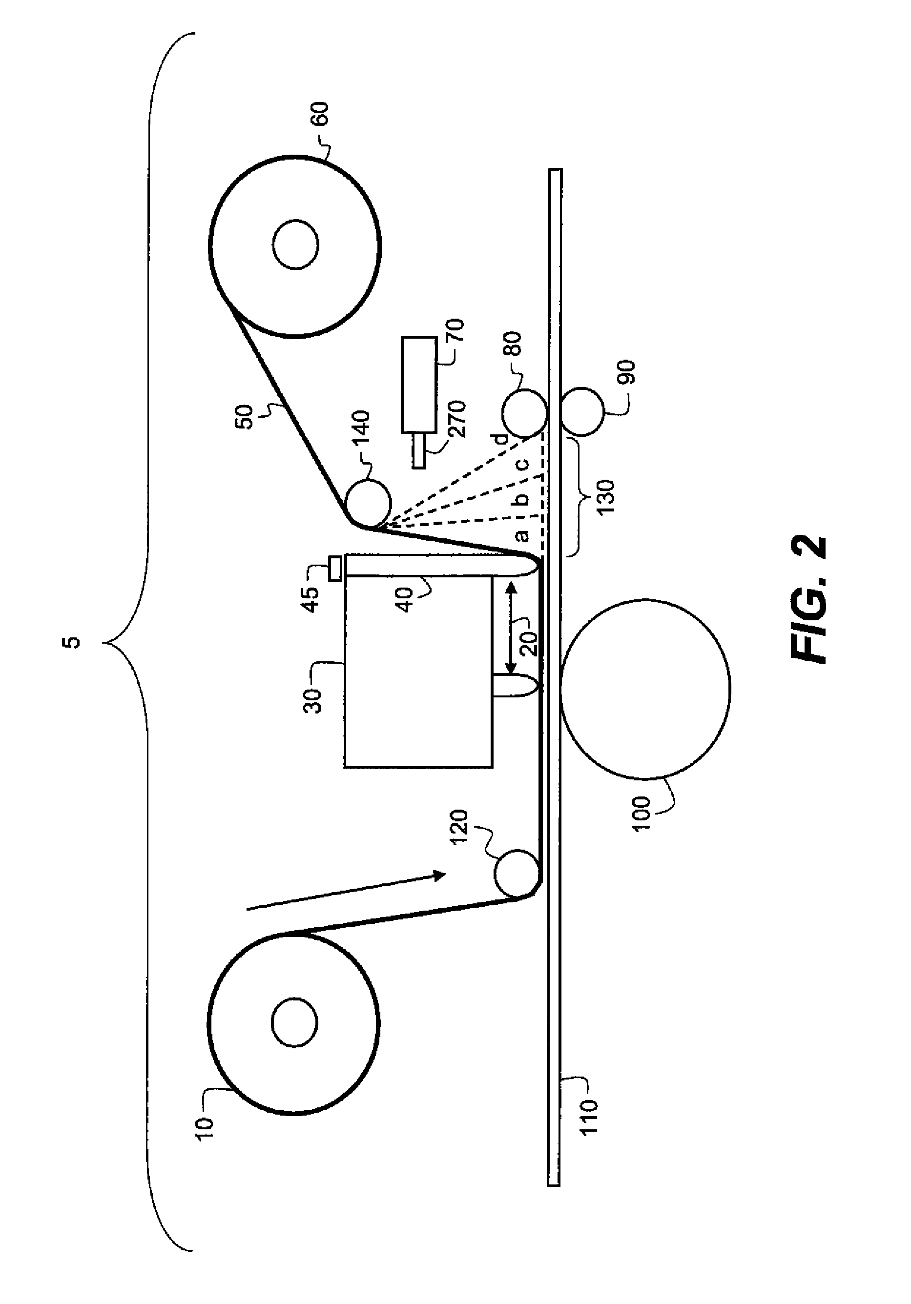

Image

  • Method for controlling peel position in a printer
  • Method for controlling peel position in a printer
  • Method for controlling peel position in a printer

Examples


Embodiment Construction

[0033]The present description will be directed in particular to methods and / or elements forming part of, or cooperating more directly with, apparatus in accordance with the present invention. It is to be understood that elements not specifically shown or described may take various forms well known to those skilled in the art.

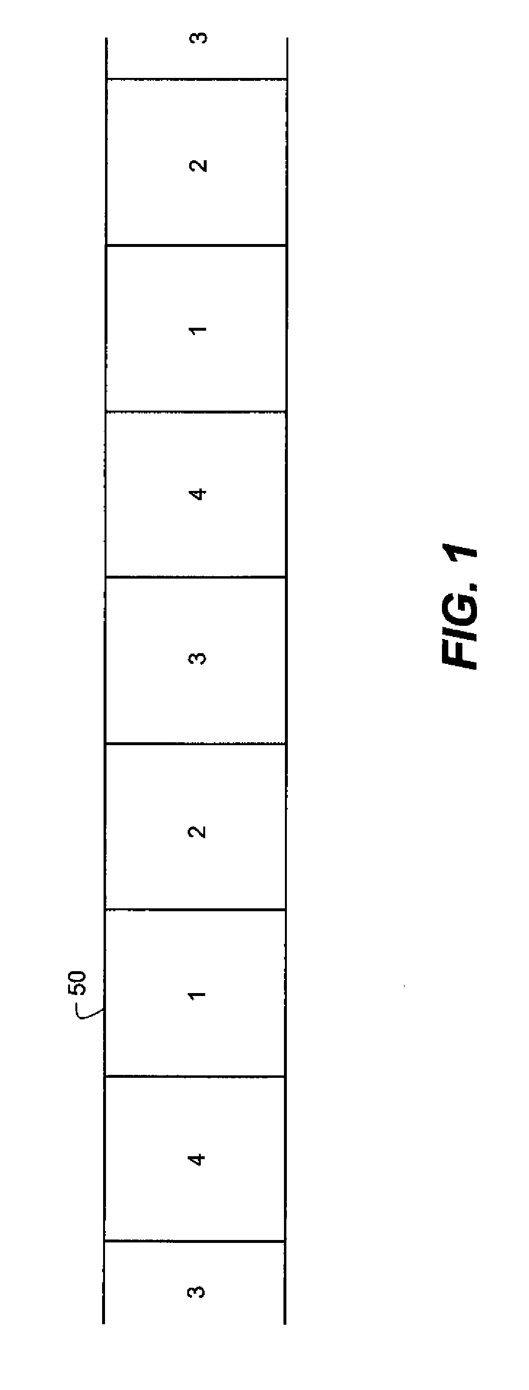
[0034]FIG. 1 depicts a typical multi-color dye donor web or ink ribbon 50 that is used in a dye transfer or thermal printer apparatus and method. The dye donor web 50 has a repeating series (only one completely shown) of three different rectangular-shaped color sections or patches such as a first color section 1 (usually yellow), a second color section 2 (usually magenta) and a third color section 3 (usually cyan). In addition, there is usually a transparent overcoat section or patch 4 (laminate) immediately after the third color section 3. The repeating series of dye donor web sections is applied to the same area of a second web or receiver sheet 110 shown in F...


PUM


Abstract

A method for maintaining a peel location and for peeling a layer of media from a surface in a thermal printer. An optical probe, that includes a light source and a photodetector, transmits light from the optical probe toward a first web. The web reflects a portion of the transmitted light onto the photodetector, which then outputs an electrical signal which is compared with a preselected signal level and the difference between them provides an indication as to how much adjustment the peel location requires. Adjusting the peel location may comprise changing environmental characteristics of the first web or the second web (surface) or adjusting a tension of the first or second web. The difference between the measured electrical signal levels is related to a physical distance of the first web from the desired peel location.

Description

CROSS REFERENCE TO RELATED APPLICATION[0001]Reference is made to commonly assigned, co-pending U.S. patent application Ser. No. ______ by Marcus et al. (Docket 95883) filed of even date herewith entitled “Apparatus For Controlling Peel Position In A Printer”, the disclosure of which is incorporated herein by reference in their entireties.FIELD OF THE INVENTION[0002]The present invention relates to measurement methods and apparatuses, and more particularly to a method and apparatus to maintain a desired peel location of a first web from a second web located in a printer.BACKGROUND OF THE INVENTION[0003]A typical multi-color dye donor web that is used in a dye transfer or thermal printer has a repeating series of three different rectangular-shaped color sections or patches such as a yellow color section, a magenta color section and a cyan color section. In addition, there may be a transparent colorless laminating section immediately after the color sections.[0004]Each color section of...

Claims


Application Information

Patent Timeline
IPC IPC(8): B41J11/00
CPCB41J17/38
Inventor MARCUS, MICHAEL A.KALTENBACH, THOMAS F.
Owner EASTMAN KODAK CO
Why Eureka
Eureka Blog
Learn More