Seismic source which incorporates earth coupling as part of the transmitter resonance

a technology of seismic source and transmitter resonance, which is applied in the direction of seismic source, transducer type, geological measurement, etc., can solve the problems of poor coupling of the source to the earth, affecting the transmission efficiency of seismic energy, and affecting the relationship between signal consistency between different source actuations

Active Publication Date: 2011-03-31
ACOUSTIC ZOOM
View PDF8 Cites 30 Cited by
  • Summary
  • Abstract
  • Description
  • Claims
  • Application Information

AI Technical Summary

Problems solved by technology

A particular problem encountered during transmitting acoustic energy into the subsurface as experienced in seismic exploration practices is relatively poor coupling of the source to the earth due to impedance mismatch between the air and the soil or ground conditions.
The

Method used


Image

  • Seismic source which incorporates earth coupling as part of the transmitter resonance
  • Seismic source which incorporates earth coupling as part of the transmitter resonance

Examples


Embodiment Construction

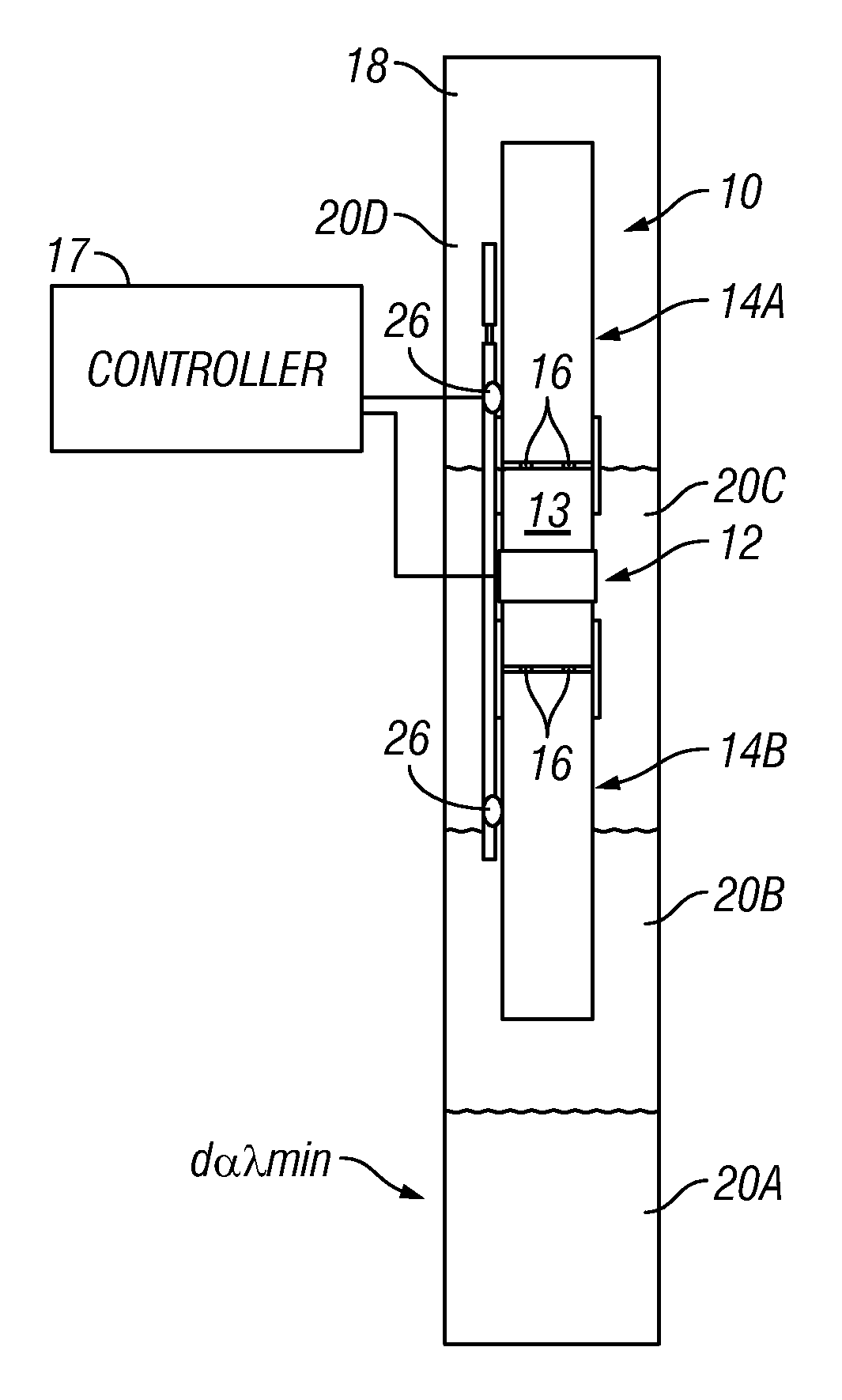
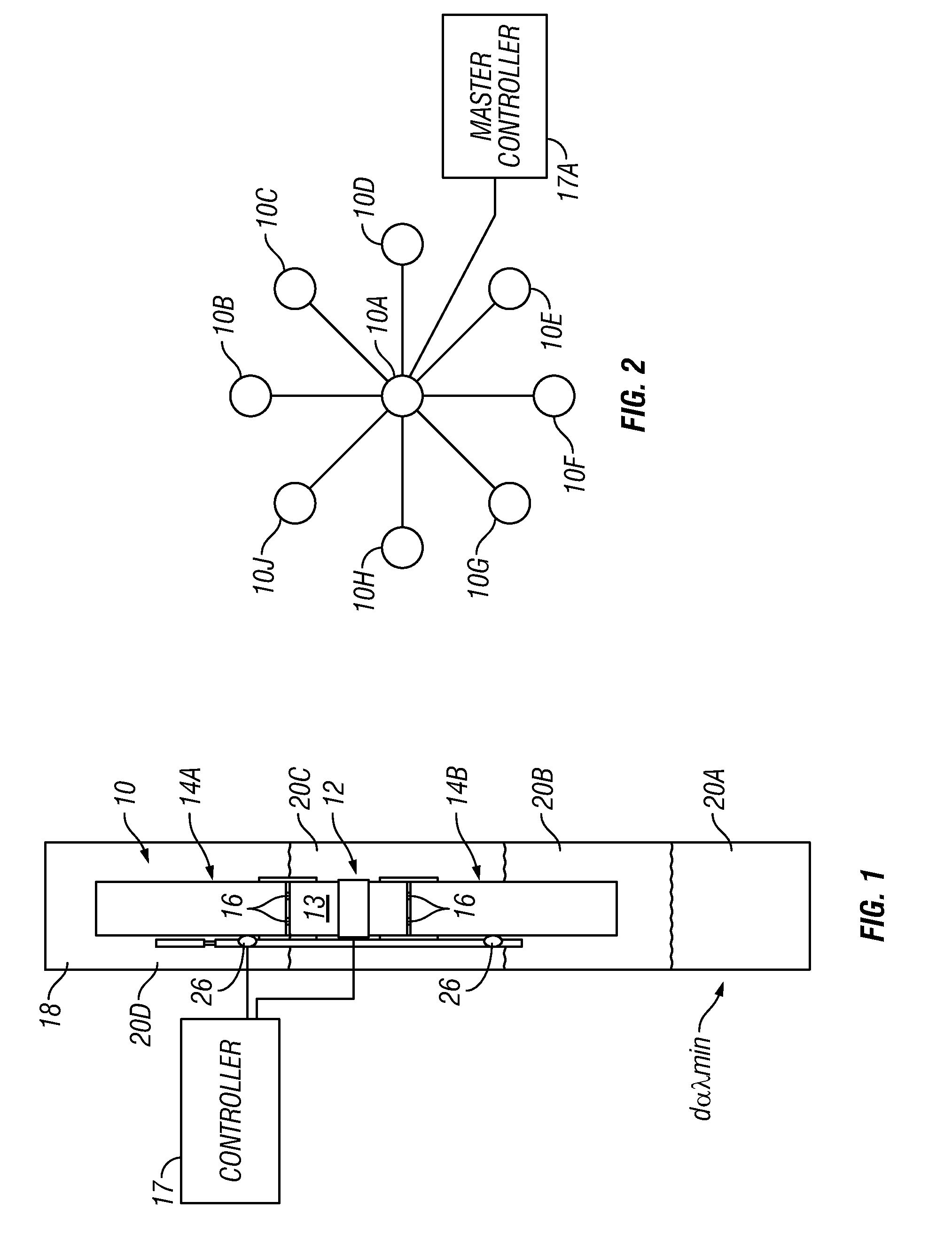
[0014]The principle of the invention described herein includes an impedance matching medium to a mechanism of long resonator tubes that generate the sound. The foregoing structure can provide a better impedance match to the subsurface. The resonator tube or coupling waveguide is an integral part of the transmitter (source) design and of its resonance. This is particularly relevant when considering the difficulties in transmitting into the subsurface suitable high intensity signals of typically low frequencies (50 Hz to 300 Hz) generally associated with and targeted for seismic tomography mapping.

[0015]For an acoustic transducer to radiate power then for a given drive level the displacement amplitude of, for example, a piston or of the moving mechanism is determined by the radiation resistance. The radiation resistance for a piston of diameter greater than λ / 2π (wherein λ is the energy wavelength) is approximately ρcA, where A is the piston area and, ρ is the density of the formation...


PUM


Abstract

An acoustic energy source for imparting acoustic energy into the Earth's subsurface includes an electrically driven transducer coupled to a source of swept frequency alternating current. A tunable Helmholtz resonator is disposed proximate the transducer. In one example, the resonator has a tuning device configured to maintain a resonant frequency substantially equal to an instantaneous frequency of the alternating current. The tuning device includes an actuator coupled to a sleeve, wherein the sleeve is disposed over selected numbers of openings in a wall of a tube on the resonator. The transducer and the resonator are disposed in a wellbore drilled through rock formations. The wellbore has a plurality of layers of fluid therein, each layer thereof having a different density and/or viscosity.

Description

CROSS-REFERENCE TO RELATED APPLICATIONS[0001]Priority is claimed from U.S. Provisional Application No. 61 / 245,707 filed on Sep. 25, 2009STATEMENT REGARDING FEDERALLY SPONSORED RESEARCH OR DEVELOPMENT[0002]Not applicable.BACKGROUND OF THE INVENTION[0003]1. Field of the Invention[0004]The invention relates generally to the field of seismic exploration of subsurface rock formations. More specifically, the invention relates to seismic energy sources used to illuminate the subsurface rock formations for seismic evaluation thereof.[0005]2. Background Art[0006]Seismic exploration of subsurface rock formations includes so called “controlled source” or “active source” exploration, wherein one or more seismic energy sources are deployed above an area of the subsurface to be evaluated. The deployment may be near the land surface for land based surveys or in the water or on the water bottom for marine surveys. The sources are energized, and energy reflected from subsurface acoustic impedance bo...

Claims


Application Information

Patent Timeline
IPC IPC(8): H04R17/00B06B1/06
CPCG01V1/137G01V1/159G01V1/52
Inventor GULGNE, JACQUES Y.PACE, NICHOLAS G.WRIGHT, JAMES A.DINN, GARY J.
Owner ACOUSTIC ZOOM
Why Eureka
Try Eureka