Low Clearance Machined Part Mating System

a technology of low clearance and machined parts, applied in the direction of program control, instrumentation, semiconductor/solid-state device testing/measurement, etc., can solve the problem that the operator may generally induce tilt and position errors

Inactive Publication Date: 2011-04-07
SONNAX TRANSMISSION CO
View PDF18 Cites 15 Cited by
  • Summary
  • Abstract
  • Description
  • Claims
  • Application Information

AI Technical Summary

Problems solved by technology

When inserting a first part into the holding device, the operator may generally induce tilt and position error relative to the non-contact micrometer.

Method used


Image

  • Low Clearance Machined Part Mating System
  • Low Clearance Machined Part Mating System
  • Low Clearance Machined Part Mating System

Examples


Embodiment Construction

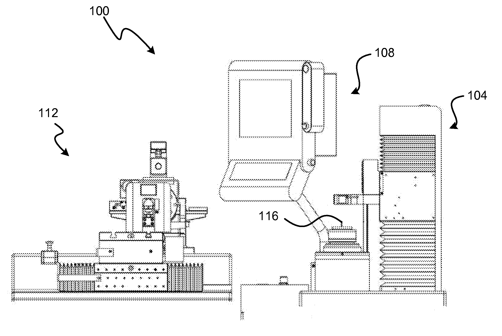
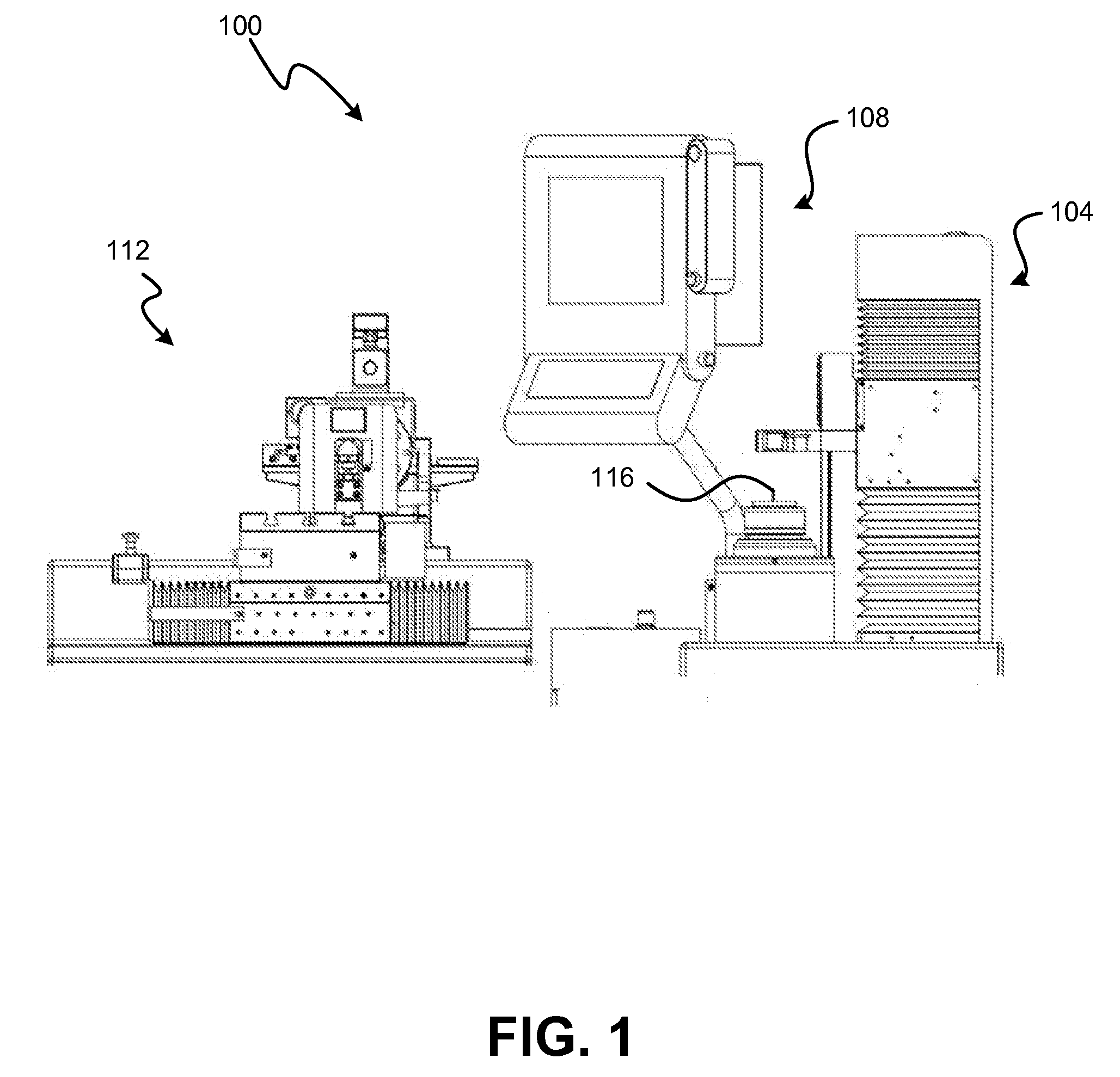
[0017]Generally, low clearance machined part mating system 100 is suitable for the volume manufacture of mating parts that slidably engage one another at precise clearances. As will be discussed more fully below, an exemplary embodiment of low clearance machined part mating system 100 contemporaneously obtains measurements sufficient to calculate the size of and the geometric errors associated with a first part and then uses the calculations to create a second part. The resulting slidable clearance tolerance, i.e., proximity to the desired clearance, between the two parts may be consistently as little as 0.00005 inch, or even less in some cases, which may be considered a reduction of more than 20 times the clearance tolerance levels achievable using prior art techniques. Less precise clearance tolerances are also obtainable with system 100.

[0018]In one embodiment of the present disclosure, the process by which mating parts are made can be performed in less than about 9 minutes. Howe...


PUM

PropertyMeasurementUnit
sizeaaaaaaaaaa
distanceaaaaaaaaaa
dimensionaaaaaaaaaa

Abstract

A device, system, and method for generating low clearance slidably mated parts. In an exemplary embodiment, the system includes a measurement device having a non-contact micrometer capable of coincidentally indicating opposing edge data, rotational and linear air bearing slides, and a holding device. The non-contact micrometer allows for measurement of a plurality of parameters of a first part including the diameter and the difference between an edge of the first part and a reference point. The coincidental measurements are used to determine the size and geometric errors associated with the first part after suitable error elimination. In an exemplary system, a processing machine may be instructed by the measurement device to remove material from a second part so that the first part and the second part when mated together have a very low clearance tolerance level, e.g., as little as 0.00005 inches or less.

Description

FIELD OF THE INVENTION[0001]The present invention generally relates to the field of process machining for mated parts. In particular, the present invention is directed to an apparatus and methods for machining mating parts with low clearance requirements.BACKGROUND[0002]Manufacturing a set of mating parts, e.g., a sleeve with a bore and a spool valve that is slidably received in the bore, with very small clearances is challenging, particularly with respect to low-cost parts. Typically, in order to achieve very small clearances, a batch of one part, e.g., Part A, having a specified size and certain geometric tolerances, is made and then a batch of its corresponding part, e.g., Part B, having a specified size and certain geometric tolerances, is made. Under statistical theory, both parts A and B, individually, would exhibit a normal distribution around a mean, with an equal number of parts in the batch being higher and lower than the average part size. Thus, the parts could be “matche...

Claims


Application Information

Patent Timeline
Patent Type & Authority Applications(United States)
IPC IPC(8): G01M19/00B23P21/00
CPCB23P17/00Y10T29/49778G05B19/401G05B2219/37345G01B5/0002H01L22/20H01L2924/0002B23P21/00Y10T29/4978Y10T29/49861Y10T29/53022Y10T29/49771Y10T29/49769H01L2924/00
Inventor DEROCHE, WILLIAM M.EMGE, GARRY J.
Owner SONNAX TRANSMISSION CO
Why Eureka
Try Eureka