Applicator instruments having curved and articulating shafts for deploying surgical fasteners and methods therefor

a technology of articulating shafts and surgical fasteners, which is applied in the field of surgical fasteners, can solve the problems of limited ability of prior art devices to engage the fastener, damage the surgical fastener, and prior art devices that do not advance the fastener fast, so as to improve the ability of surgical fasteners to penetrate, improve the holding force, and improve the effect of strength and shorter tip designs

Active Publication Date: 2011-04-07
ETHICON LLC
View PDF81 Cites 178 Cited by
  • Summary
  • Abstract
  • Description
  • Claims
  • Application Information

AI Technical Summary

Benefits of technology

[0089]In one embodiment, surgical fasteners have one or more barbs with “living hinge” features. The living hinges enable the barbs to collapse easily during insertion but flare outwardly during attempts to remove the surgical fasteners.
[0090]In one embodiment, the pointed insertion tips of the surgical fasteners are cut or have defined chisel points, which enable the insertion tips to cut during insertion, thereby improving the ability of the surgical fasteners to penetrate difficult materials such as GORE®dual mesh. Insertion tips having compound cut or chiseled angles may also be used to allow for stronger, yet shorter tip designs.
[0091]In one embodiment, surgical fasteners may have conical-shaped insertion tips that create a puncture rather than a cut, thereby improving holding force. Although the present invention is not limite

Problems solved by technology

The first type of prior art device is limited in its ability to engage the fastener in a secure manner to assure the fastener's proper insertion into tissue.
The first “hammer-like” prior art device may also damage the surgical fastener due to impact force or may require the use of a massive fastene

Method used


Image

  • Applicator instruments having curved and articulating shafts for deploying surgical fasteners and methods therefor
  • Applicator instruments having curved and articulating shafts for deploying surgical fasteners and methods therefor
  • Applicator instruments having curved and articulating shafts for deploying surgical fasteners and methods therefor

Examples


Embodiment Construction

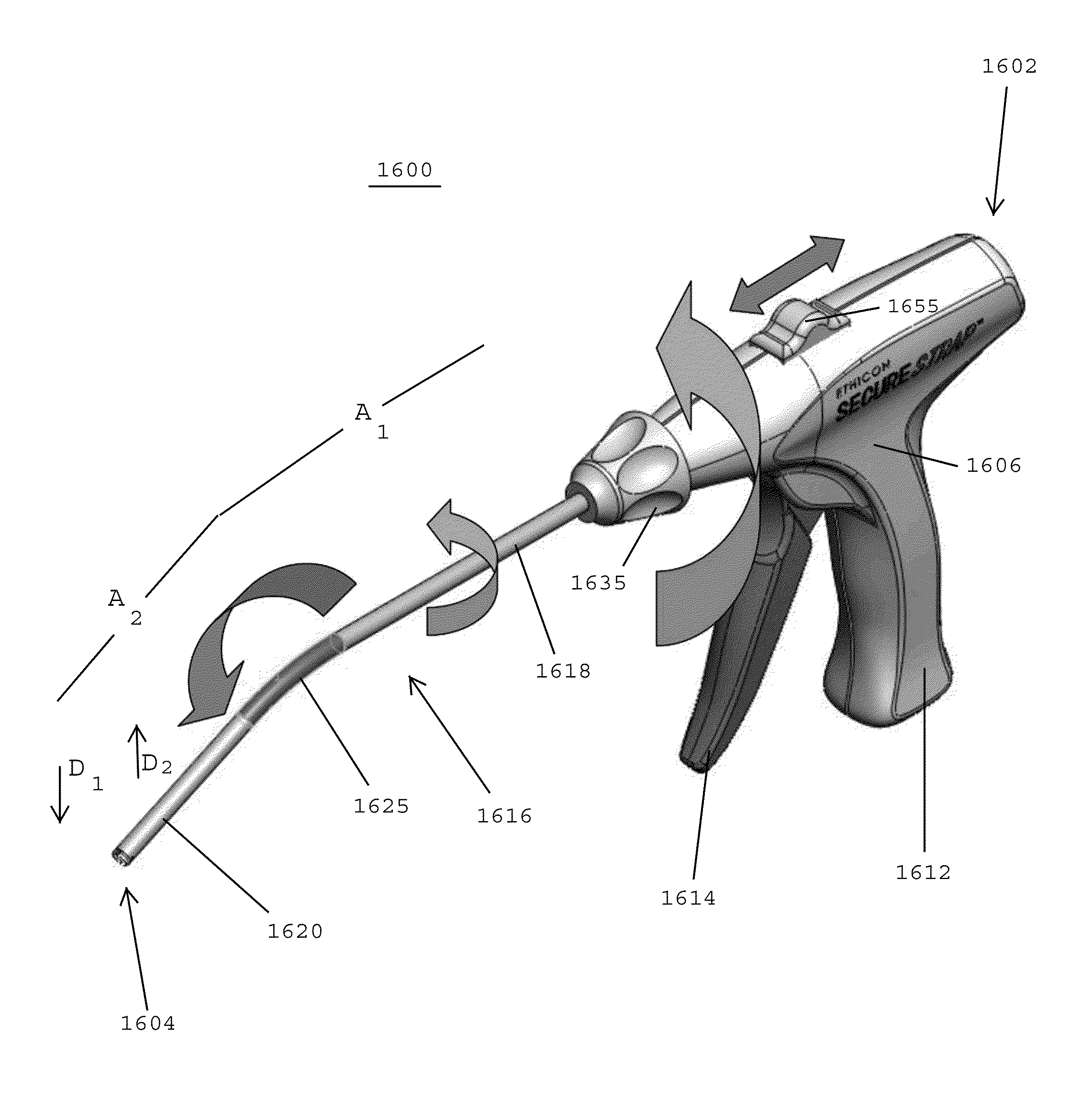
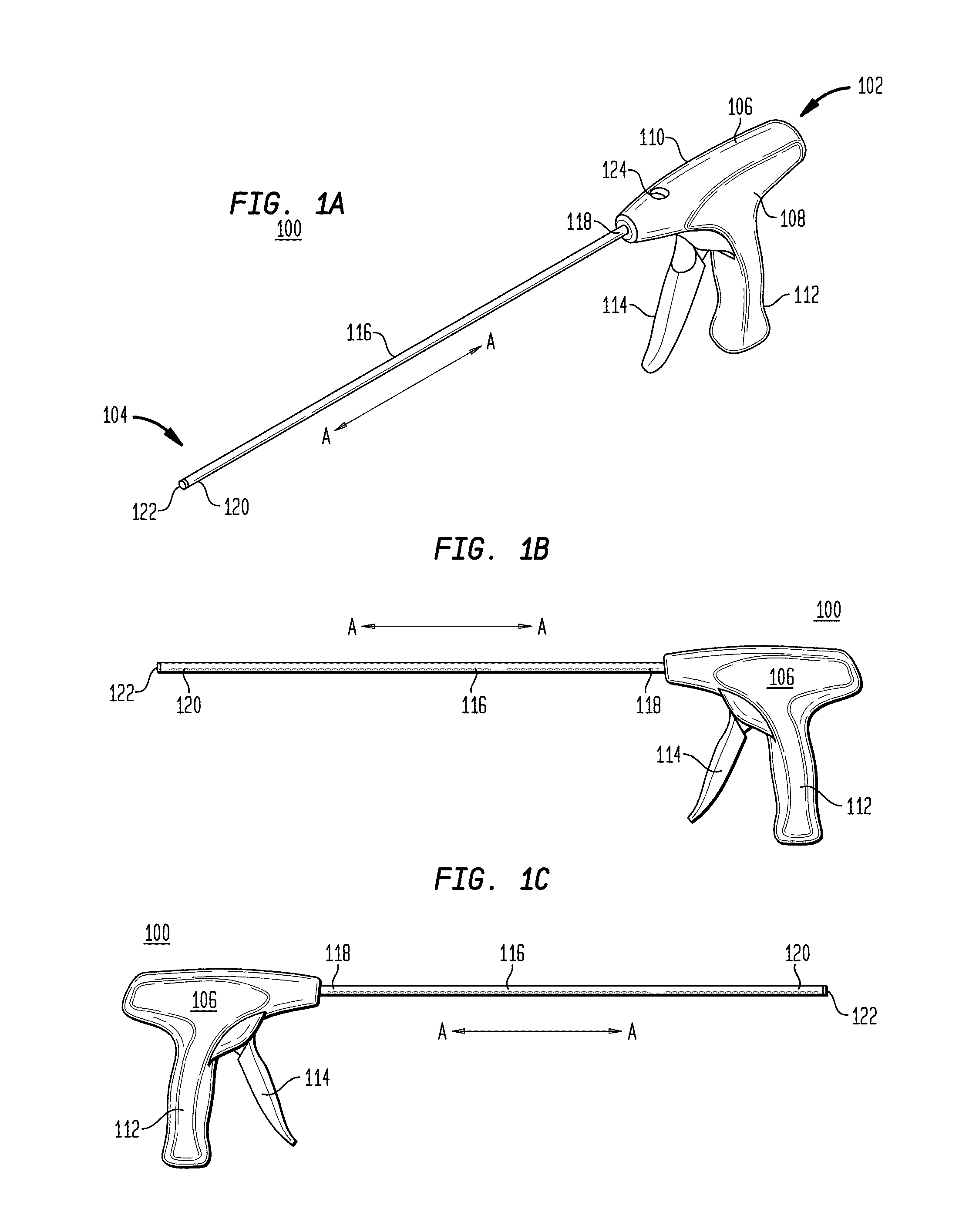
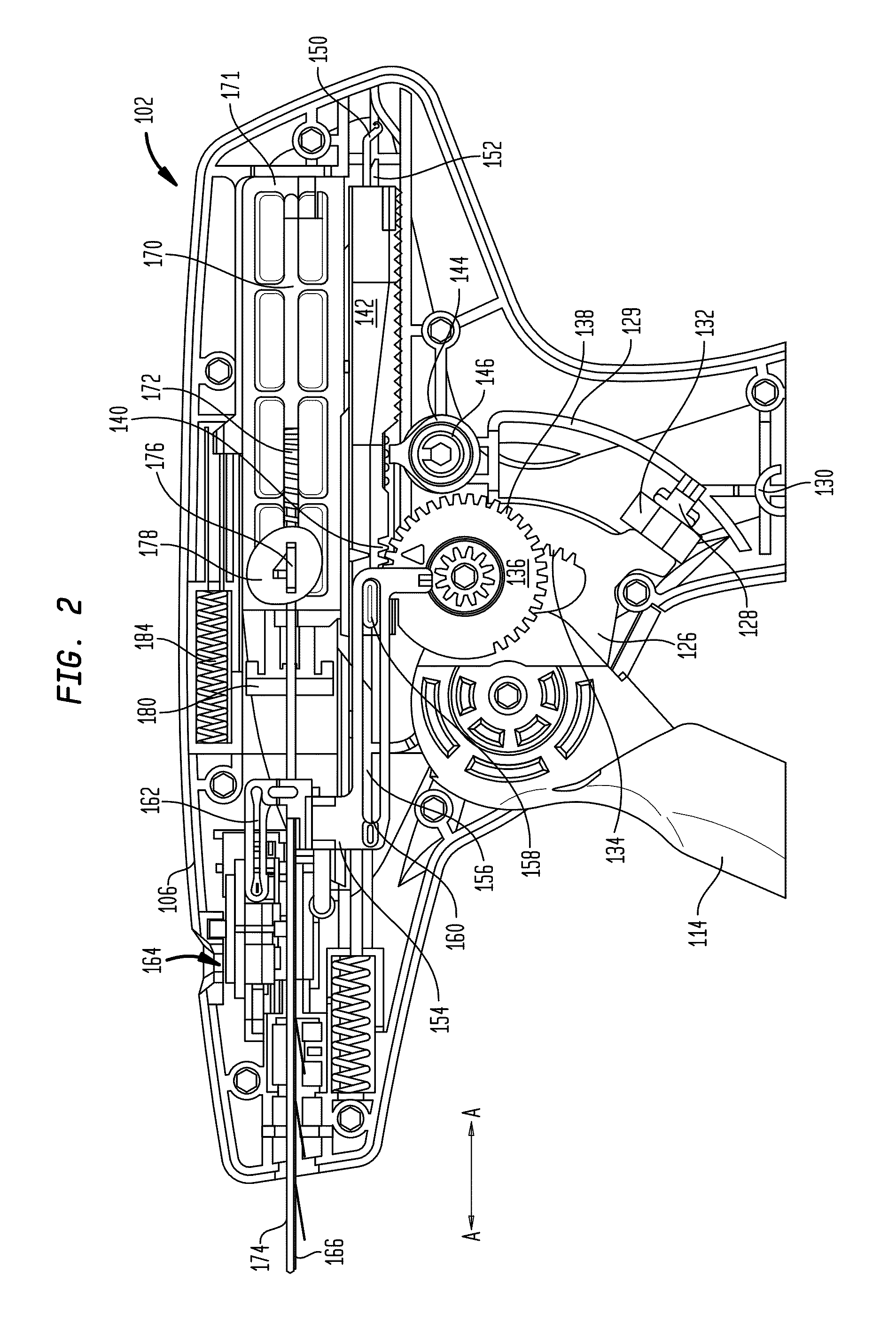
[0165]Referring to FIGS. 1A-1C, in one embodiment, an applicator instrument 100 for dispensing surgical fasteners has a proximal end 102 and a distal end 104. The applicator instrument 100 includes a housing 106 that contains a firing system for deploying the surgical fasteners. The housing 106 has a left cover 108 and a right cover 110. The left and right covers 108, 110 have lower ends forming a hand grip 112. The applicator instrument 100 preferably includes a trigger 114 that may be squeezed for dispensing the surgical fasteners from the distal end 104 of the instrument. In one embodiment, the applicator instrument 100 holds a plurality of surgical fasteners, whereby a single surgical fastener is dispensed from the distal end 104 of the applicator instrument each time the trigger 114 is squeezed. In one embodiment, the applicator instrument holds a plurality of surgical fasteners that are advanced toward the distal end of the outer tube 116 each time the trigger 114 is squeezed....


PUM

PropertyMeasurementUnit
Angleaaaaaaaaaa
Timeaaaaaaaaaa
Angleaaaaaaaaaa

Abstract

An applicator instrument for dispensing surgical fasteners includes a housing and a curved shaft. Surgical fasteners are disposed within the curved shaft for being dispensed from the distal end of the curved shaft. An advancer is disposed inside the curved shaft for shifting the surgical fasteners one position closer to the distal end of the curved shaft each time the advancer moves distally. A firing element is disposed inside the curved shaft and is movable between the proximal and distal ends of the curved shaft for dispensing the surgical fasteners from the distal end of the curved shaft. A staging assembly is adapted to receive a leading one of the surgical fasteners from the advancer as the advancer moves distally to shift the leading surgical fastener into substantial alignment with the firing element when the advancer moves proximally.

Description

CROSS REFERENCE TO RELATED APPLICATIONS[0001]The present application is a continuation-in-part of U.S. patent application Ser. No. 12 / 464,143, filed May 12, 2009, which is related to the following commonly assigned U.S. patent applications: U.S. patent application Ser. No. 12 / 464,151, filed May 12, 2009, U.S. patent application Ser. No. 12 / 464,165, filed May 12, 2009, and U.S. patent application Ser. No. 12 / 464,177, filed May 12, 2009. The disclosures of the above-identified patent applications are hereby incorporated by reference herein.BACKGROUND OF THE INVENTION[0002]1. Field of the Invention[0003]The present invention generally relates to surgical fasteners, and more specifically relates to applicator instruments, systems and methods for deploying surgical fasteners.[0004]2. Description of the Related Art[0005]Hernia is a condition where a small loop of bowel or intestine protrudes through a weak place or defect within the abdominal muscle wall or groin of a patient. This condit...

Claims


Application Information

Patent Timeline
IPC IPC(8): A61B17/068
CPCA61B17/0642A61B2017/2904A61B17/0682A61B2017/2923A61B2019/4836A61B17/064A61B2017/2905A61B2090/0807
Inventor CARDINALE, MICHAELCOHN, SIMON
Owner ETHICON LLC
Why Eureka
Try Eureka