
Fluid ejection assembly having a mounting substrate

a technology of mounting substrate and fluid feed slot, which is applied in the direction of metal working apparatus, printing, manufacturing tools, etc., can solve the problems of insufficient strength, flat and stable mounting substrate, and inability to make fluid feed slots, so as to reduce the width of the fluid feed slot, reduce the size, and reduce the effect of attachmen

Inactive Publication Date: 2011-04-07
EASTMAN KODAK CO
View PDF3 Cites 39 Cited by
  • Summary
  • Abstract
  • Description
  • Claims
  • Application Information

AI Technical Summary

Benefits of technology

[0013]The present invention relates to a fluid ejection assembly that includes an injection-molded mounting substrate that is formed by a two-shot injection-molding process, wherein a housing portion of the mounting substrate is formed by a first shot of the two-shot molding process, and a fluid passageway portion of the mounting substrate is formed within the housing portion by a second shot of the two-shot molding process. In a feature of the present invention, the two-shot injection-molded mounting substrate of the present invention provides an attachment surface for a fluid ejection device at a surface of the fluid passageway portion that is formed by the second shot. In a further feature of the present invention, with the two-shot molding process it is possible to reduce the width of the fluid feed slots and the lands between the fluid feed slots of

Problems solved by technology

The problem that remains is providing a mounting substrate having a die-attach portion with fluid feed slots at the same spacing as the fluid inlet spacing on the printhead die.
It is difficult to make fluid feed slots at a center-to-center spacing of less than one millimeter in a single injection molding process step and still provide sufficient strength in the mounting substrate.
It is found that such thin wall thickness may not provide a sufficiently strong, flat and stable mounting substrate.
Alternatively, if the walls or other features in the rest of mounting substrate were made substantially thicker than the lands between the slots, the molding material would not flow in a uniform manner to fill both the thick walls and the thin lands.
As a result, the die-attach surface can warp, so that it is insufficiently flat to allow the printhead die to be adhesively attached with reliable fluid seals between adjacent fluid feed slots.
Such knit lines are built-in discontinuities and stress concentrations which can lead to deformation and failure in the part.
Ceramic is higher in cost than plastic.
With ceramic, it is further difficult to provide for desired reduced center-to-center spacing of fluid feed slots, which enable the size the printhead substrate to be reduced.
Accordingly, providing a low cost printhead substrate that includes reduced size fluid feed slots and lands there-between when using ceramic may be difficult.
As noted above, drawbacks of using the ceramic insert molded substrate approach are cost (ceramic is relatively expensive) and the fact that there are size limitations on the slots widths and pitches (due to the manufacturing limitations of ceramic).
Smaller dimensions can be achieved with a ceramic injection molding process, but this will typically increase the cost of the part by about 2-4 times.
However, a problem with this approach involves getting sufficient strength in the substrate to provide a stable die mounting surface.
Another problem relates to controlling flatness on the die mounting surface of a plastic substrate which can be difficult because of the sink that occurs during the molding process.
Finally, most plastics have high CTE's (≈25-50 ppm / ° C. depending on the type of material) which are much higher than silicon and as a result induce high stresses on the silicon printhead die.

Method used


Image

  • Fluid ejection assembly having a mounting substrate
  • Fluid ejection assembly having a mounting substrate
  • Fluid ejection assembly having a mounting substrate

Examples


Embodiment Construction

[0028]The present description will be directed in particular to elements forming part of, or cooperating more directly with, an apparatus in accordance with the present invention. It is to be understood that elements not specifically shown or described may take various forms well known to those skilled in the art.

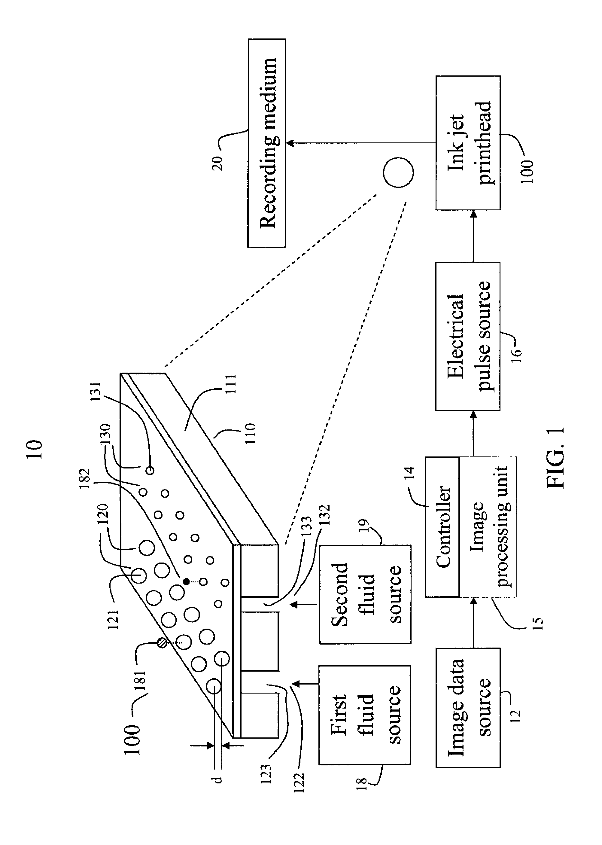
[0029]Referring to FIG. 1, a schematic representation of an inkjet printer system 10 is shown, for its usefulness with the present invention and is fully described in U.S. Pat. No. 7,350,902, and is incorporated by reference herein in its entirety. Inkjet printer system 10 includes an image data source 12, which provides data signals that are interpreted by a controller 14 as being commands to eject drops. Controller 14 includes an image processing unit 15 for rendering images for printing, and outputs signals to an electrical pulse source 16 of electrical energy pulses that are inputted to an inkjet printhead 100, which includes at least one inkjet printhead die 110. An in...


PUM

PropertyMeasurementUnit
Angleaaaaaaaaaa
Distanceaaaaaaaaaa
Distanceaaaaaaaaaa

Abstract

The present invention relates to a fluid ejection assembly that includes an injection-molded mounting substrate that is formed by a two-shot injection molding process, wherein a housing portion of the mounting substrate is formed by a first shot molding, and a die-attach portion of the mounting substrate is formed within the housing portion by a second shot molding. The die-attach portion is made of a material having a low coefficient of thermal expansion along a direction that is parallel to a fluid passageway in the die attach portion.

Description

CROSS REFERENCE TO RELATED APPLICATION[0001]Reference is made to commonly-assigned, U.S. patent application Ser. No. 12 / 338,211 filed Dec. 18, 2008, entitled INJECTION MOLDED MOUNTING SUBSTRATE in the name of Brian G. Price incorporated herein by reference.FIELD OF THE INVENTION[0002]The present invention relates to a fluid ejection assembly that includes a mounting substrate for a fluid ejection device. The mounting substrate is made by utilizing two separate molding steps in a two-shot molding process.BACKGROUND OF THE INVENTION[0003]A mounting substrate for a fluid ejection device, such as an inkjet printhead, has conventionally been made by a single molding process which forms both the die-attach portion for the fluid ejection device(s), including the fluid feed channels or slots with lands there-between, and a housing portion including alignment and fastening features, such as bolt holes. The mounting substrate should be sufficiently strong that it does not deform during fabric...

Claims


Application Information

Patent Timeline
IPC IPC(8): B41J2/14B21D53/76B23P11/00
CPCB29C45/0046B29C45/16B29C2045/1682Y10T29/49401B41J2/16B41J2/1637Y10T29/49826B29K2995/0012
Inventor CIMINELLI, MARIO J.VIANCO, SR., JAMES E.PETRUCHIK, DWIGHT J.
Owner EASTMAN KODAK CO
Features
  • Generate Ideas
  • Intellectual Property
  • Life Sciences
  • Materials
  • Tech Scout
  • Unparalleled Data Quality
  • Higher Quality Content
  • 60% Fewer Hallucinations
Learn More