Imaging apparatus detecting foreign object adhering to lens

a technology of imaging apparatus and foreign objects, applied in the field of imaging apparatus, can solve the problems of difficult application of lens to digital cameras that require versatility, high cost of lens, and large size of lens itsel

Inactive Publication Date: 2011-04-07
SANYO ELECTRIC CO LTD
View PDF14 Cites 46 Cited by
  • Summary
  • Abstract
  • Description
  • Claims
  • Application Information

AI Technical Summary

Benefits of technology

[0010]According to an aspect of the present invention, an imaging apparatus includes: an imaging unit having an imaging surface on which an optical image of a subject field passing through a lens is emitted, which generates an image signal corresponding to the optical image of the subject field by photoelectric conversion; an aperture control unit which controls an aperture of the lens; a shutter unit which controls exposure time for the imaging unit; an exposure adjustment unit which adjusts an exposure value ...

Problems solved by technology

However, although the focusing determination unit described above is based on the premise that a focus position of the focus lens is set on the surface of the optical component, such a lens costs high, and the lens itself is large in size.
Therefore, there has been a problem that it is difficult to apply the lens to digital cameras that require versatility.
In addition, while the adhering matter presence/absence detection unit described above requires the reference image to determine the presence or absence of adhering matter on the camera, in...

Method used


Image

  • Imaging apparatus detecting foreign object adhering to lens
  • Imaging apparatus detecting foreign object adhering to lens
  • Imaging apparatus detecting foreign object adhering to lens

Examples


embodiment 1

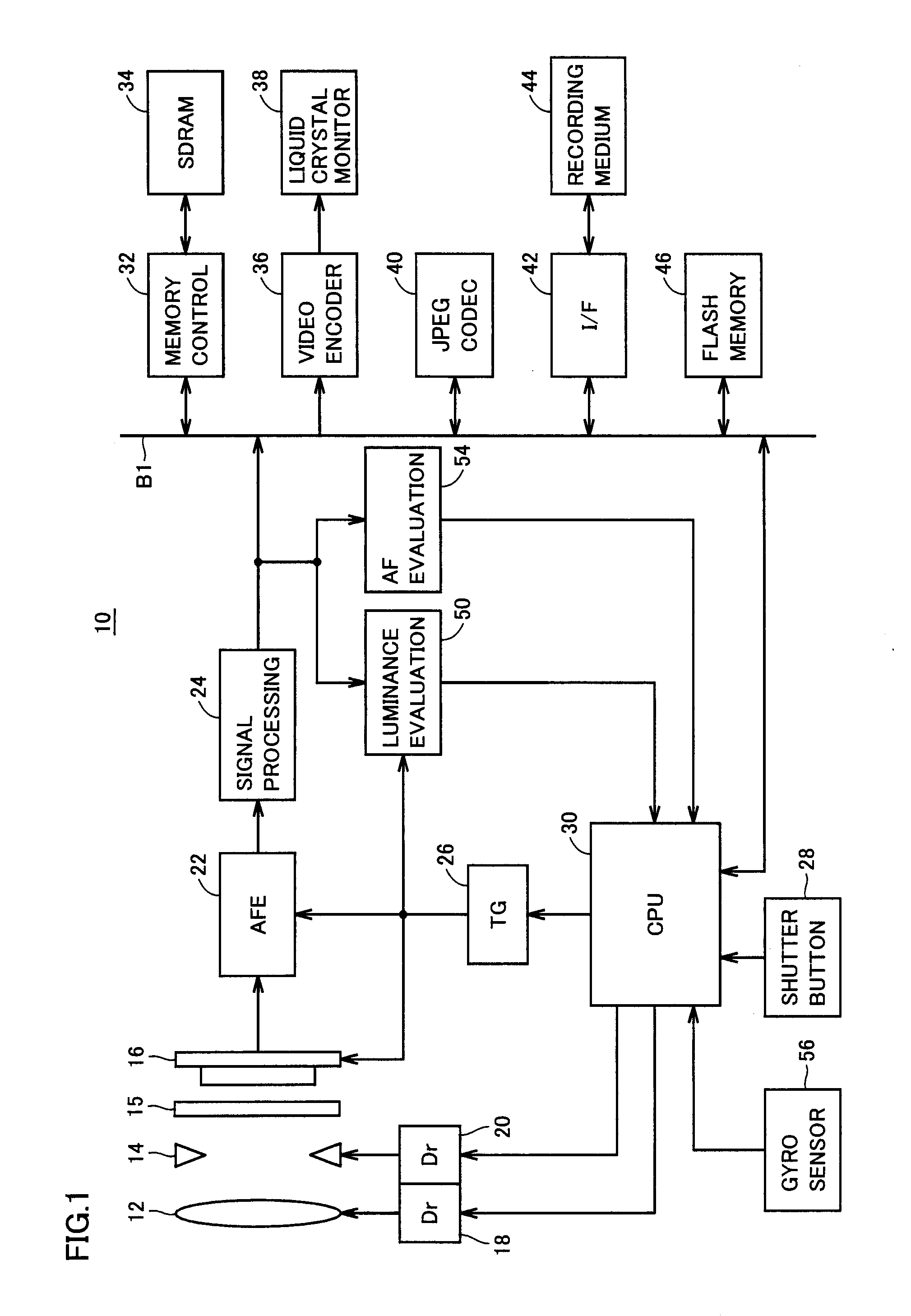
[0024]FIG. 1 is a schematic configuration diagram showing main portions of a digital camera 10 as an imaging apparatus in accordance with Embodiment 1 of the present invention.

[0025]Referring to FIG. 1, in digital camera 10, an optical image of a subject field is emitted through an optical lens 12 to a light receiving surface, that is, an imaging surface, of an imaging element 16. An aperture mechanism 14 adjusts the amount of light passing through optical lens 12. A shutter 15 adjusts time for which light from the subject field is incident on the imaging surface of imaging element 16 (exposure time). Imaging element 16 generates an electric charge corresponding to brightness / darkness of the optical image of the subject field formed on the imaging surface, that is, a raw image signal, by photoelectric conversion. As imaging element 16, for example, a CCD (Charge Coupled Device) or a CMOS (Complementary Metal-Oxide Semiconductor) is used.

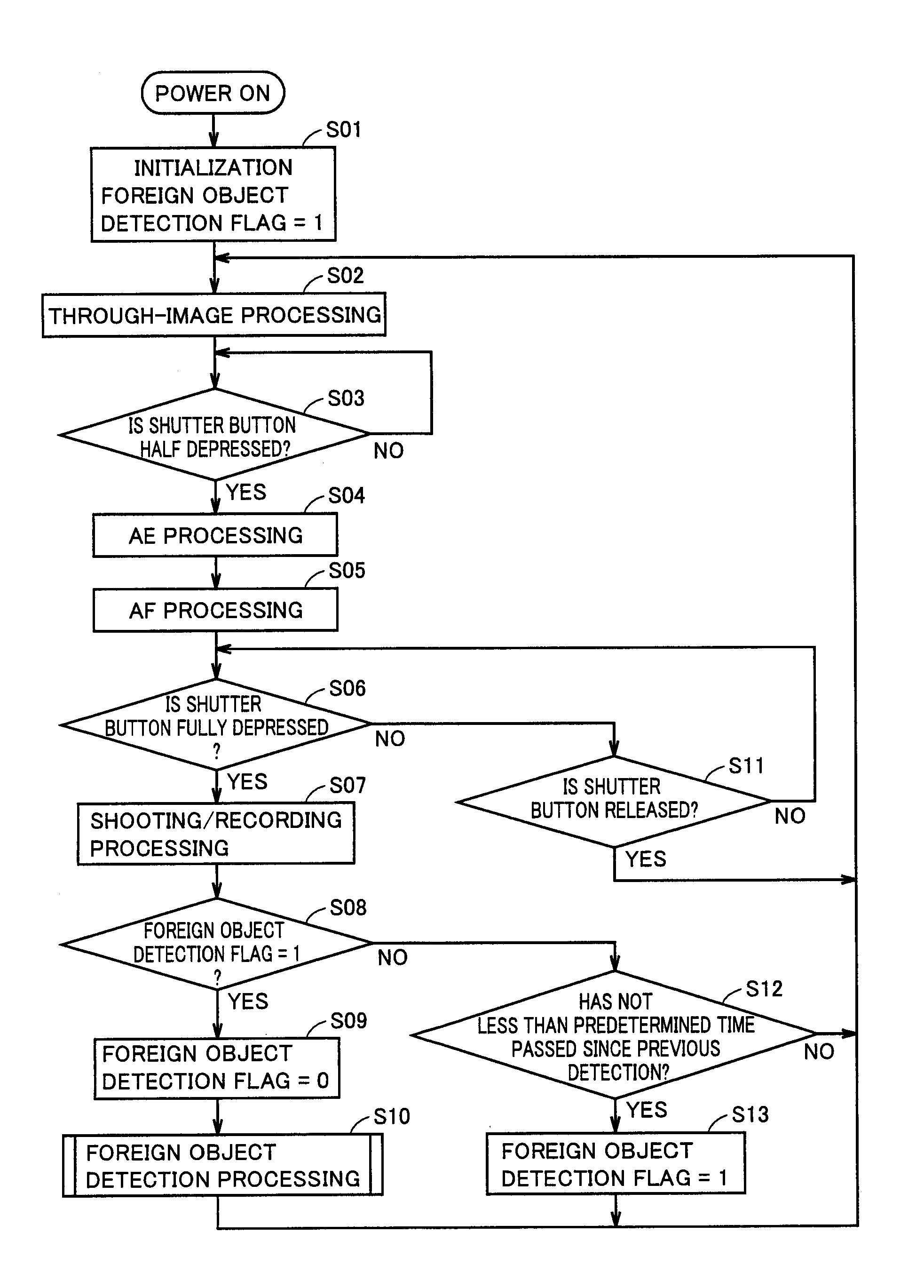
[0026]When power is on, through-image processi...

embodiment 2

[0083]In Embodiment 1 described above, image 1 and image 2 having different depths of field are shot in a state where the focus position of optical lens 12 is set beforehand at the proximate end portion. In such a configuration, the subject in the image looks blurred as shown in FIGS. 4C and 5C. Therefore, in the case where a difference in the degree of blurring of the subject between image 1 and image 2 appears as a difference in brightness between the images, there is a possibility that detection of the difference in brightness may lead to an erroneous determination that a foreign object adheres.

[0084]In foreign object detection processing in accordance with the present embodiment, as means for preventing such a problem, image 1 and image 2 are shot with the aperture changed in a state where the focus position of optical lens 12 is set on a subject.

[0085]FIG. 9 is a flowchart illustrating foreign object detection processing in accordance with Embodiment 2 of the present invention....

embodiment 3

[0087]In Embodiments 1 and 2 described above, shooting is continuously performed with the aperture changed to the open end and the small aperture end after the ordinary shooting processing is completed. Similar effects can also be obtained when shooting is performed with the aperture changed from the state set for the ordinary shooting processing.

[0088]FIGS. 10 and 11 are flowcharts illustrating foreign object detection processing in accordance with Embodiment 3 of the present invention. A control program corresponding to the flowcharts is stored in flash memory 46.

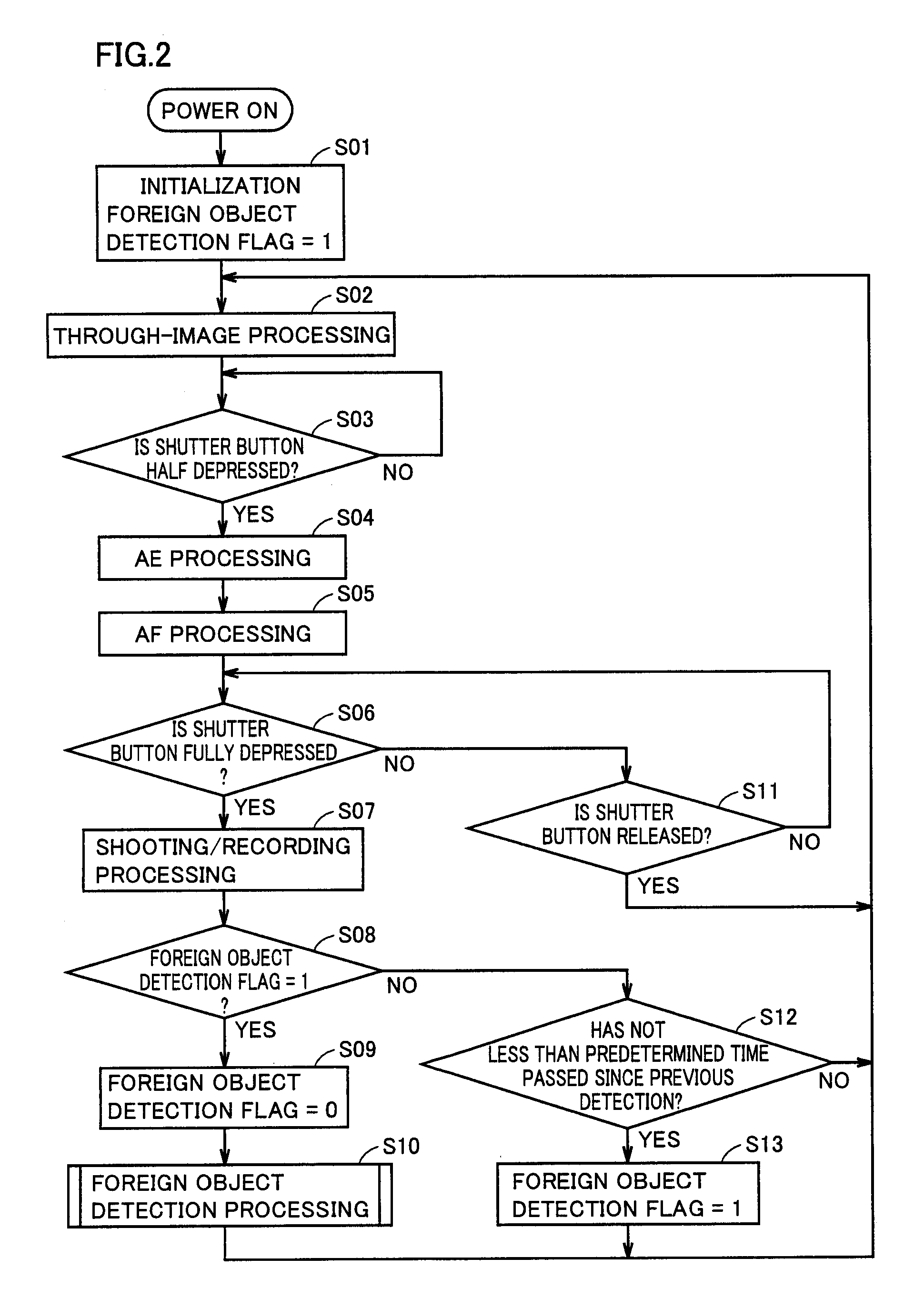
[0089]The flowchart of FIG. 10 is different from the flowchart of FIG. 2 only in that steps S07, S10 in the flowchart of FIG. 2 are replaced by steps 5071, S101.

[0090]Referring to FIG. 10, in step S06, if shutter button 28 is fully depressed (YES in step S06), CPU 30 performs the shooting / recording processing (step S071). On this occasion, the raw image signal with a high resolution output from imaging element 16 is conve...


PUM


Abstract

An imaging element having an imaging surface on which an optical image of a subject field passing through an optical lens is emitted generates an image signal corresponding to the optical image of the subject field by photoelectric conversion. An aperture mechanism controls an aperture of the optical lens. A shutter controls exposure time for the imaging element. An exposure adjustment unit adjusts an exposure value for the imaging surface based on an evaluation value of brightness of the subject field. A focus adjustment unit adjusts a focus position of the optical lens. A CPU detects a foreign object adhering to the optical lens by performing shooting under a plurality of shooting conditions in which the exposure value and the focus position are identical and aperture values are different from each other, and comparing a plurality of the image signals obtained from the imaging element during the shooting.

Description

[0001]This nonprovisional application is based on Japanese Patent Application No. 2009-230219 filed on Oct. 2, 2009 with the Japan Patent Office, the entire contents of which are hereby incorporated by reference.BACKGROUND OF THE INVENTION[0002]1. Field of the Invention[0003]The present invention relates to an imaging apparatus, and more particularly to an imaging apparatus having a foreign object detection function for detecting a foreign object adhering to an optical system.[0004]2. Description of the Related Art[0005]As an example of an imaging apparatus having a function of detecting a foreign object adhering to an optical system including a lens, there is a digital camera having an optical component provided to a lens barrel and exposed to the outside, a focus lens focusing a subject image on an image formation position, a drive unit moving the focus lens and adjusting a focus point to obtain a focusing position, a focusing determination unit determining whether or not the focu...

Claims


Application Information

Patent Timeline
IPC IPC(8): H04N5/228G03B7/00G03B17/00G03B17/02G03B17/18H04N5/225H04N5/232H04N101/00
CPCH04N5/2171H04N5/2356H04N5/232H04N23/811H04N23/52H04N23/673H04N23/743
Inventor MORI, YUKIOKIKUCHI, KENICHITAKAYANAGI, WATARU
Owner SANYO ELECTRIC CO LTD
Why Eureka
Try Eureka