Method manufacturing of fluid dynamic bearing using cutting tool that performs micro alternating drive, fluid dynamic bearing manufactured by using the method, and disk drive device using the bearing

a technology of fluid dynamic bearing and micro-alternating drive, which is applied in the direction of liquid cushion bearings, maintaining head carrier alignment, instruments, etc., can solve the problems of deviating from the designed value of dynamic pressure balance, and affecting the efficiency of the ball rolling process

Inactive Publication Date: 2011-04-07
SAMSUNG ELECTRO MECHANICS JAPAN ADVANCED TECHNOLOGY CO LTD
View PDF5 Cites 14 Cited by
  • Summary
  • Abstract
  • Description
  • Claims
  • Application Information

AI Technical Summary

Benefits of technology

[0012]By using the fluid dynamic bearing according to the above embodiment, disk drive devices having various specifications can be readily provided.

Problems solved by technology

As a result, there is a problem that a dynamic pressure generated by such a dynamic pressure groove is varied, causing a dynamic pressure balance to deviate from a designed value.
Also, there is a problem that the ball-rolling process cannot deal with the case where the depth of the dynamic pressure groove is desired to be adjusted in accordance with a distance from the end of the shaft housing hole portion.
Also, there is a problem that the ball-rolling process takes a long time because the process cannot be carried out at a high speed, and the bearing base material is likely to deform because a stress exerted thereon during the process is large, causing dimension accuracy of the sleeve after processed to be likely deteriorated.
In addition, a radius of the ball in the general ball-rolling process is difficult to be made R 0.3 mm or less.
Therefore, a fine shape having R 0.3 mm or less cannot be manufactured as a shape of the dynamic pressure groove.
Therefore, such a groove processing tool is not economical in terms of expenditures and resources, causing a major problem.
Also, there is a problem that, when intending to change the inner diameter of the cylindrical portion by even 1 μm due to a certain reason, the groove processing tool must be newly prepared and the equipment for the tool must be remodeled.

Method used


Image

  • Method manufacturing of fluid dynamic bearing using cutting tool that performs micro alternating drive, fluid dynamic bearing manufactured by using the method, and disk drive device using the bearing
  • Method manufacturing of fluid dynamic bearing using cutting tool that performs micro alternating drive, fluid dynamic bearing manufactured by using the method, and disk drive device using the bearing
  • Method manufacturing of fluid dynamic bearing using cutting tool that performs micro alternating drive, fluid dynamic bearing manufactured by using the method, and disk drive device using the bearing

Examples


Embodiment Construction

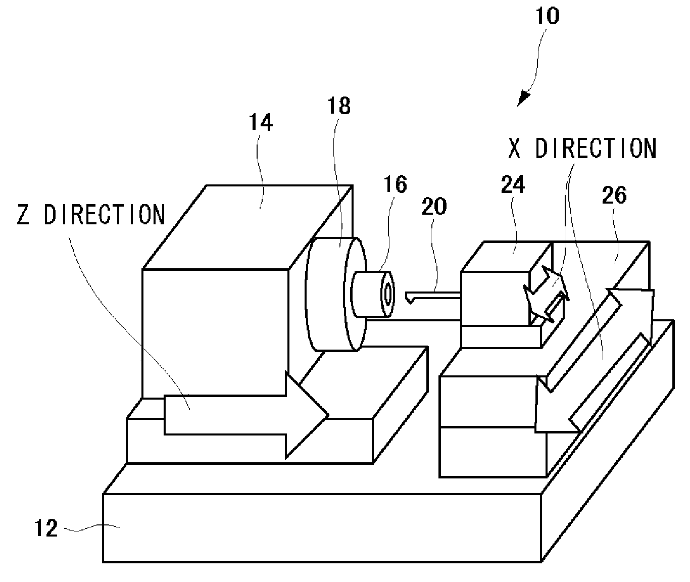
[0029]The invention will now be described by reference to the preferred embodiments. This does not intend to limit the scope of the present invention, but to exemplify the invention. FIG. 1 is a view illustrating the manufacturing equipment 10 used in the manufacturing method of the fluid dynamic bearing according to an embodiment of the present invention. A rotational drive unit 14 is arranged on the base 12. The rotational drive unit 14 holds with a chuck 18 a bearing base material (hereinafter, referred to as a “work 16”), which forms a sleeve functioning as a shaft housing member that houses a rotating shaft of the fluid dynamic bearing, so that the work 16 is rotated. A rotation speed of the rotational drive unit 14 is selected, for example, as approximately 3000 rpm. The speed is selected based on test results that: there is a problem that the speed equal to or lower than 1000 rpm makes a processing time long; and there is also a problem that the speed higher than 5000 rpm mak...


PUM

PropertyMeasurementUnit
radiusaaaaaaaaaa
displacementaaaaaaaaaa
depthaaaaaaaaaa

Abstract

A method manufacturing of a fluid dynamic bearing includes: forming a substantially linear groove having a length corresponding to a circumferential direction width of the dynamic pressure groove formed on the inner circumferential surface of a shaft housing hole portion, along the circumferential direction of a surface orthogonal to a first processing direction along the central axis direction of a work, by a byte that performs a micro alternating drive in a second processing direction orthogonal to the first processing direction; and extending the dynamic pressure groove that extends in the first processing direction by continuously forming the substantially linear grooves in the first processing direction by displacing the relative positions of the work and the byte in the first processing direction.

Description

FIELD OF THE INVENTION[0001]The present invention relates to a method manufacturing of a fluid dynamic bearing, a fluid dynamic bearing and a disk drive device provided with the fluid dynamic bearing.DESCRIPTION OF THE RELATED ART[0002]Recently, disk drive devices such as HDDs have been dramatically improved in their rotational accuracy by providing fluid dynamic bearings, and therefore those with high density and large capacity can be available. Due to this, fluid dynamic bearings and disk drive devices provided with the bearings have been mounted in a wide variety of apparatuses. Accordingly, the disk drive devices have been used in various environments, and with this, there have been demands for more inexpensive disk drive devices as well as improved characteristics such as miniaturization, light weight, low current and high stiffness.[0003]With the needs being diversified as stated above, specifications for the disk drive devices have been diversified, thereby the fluid dynamic ...

Claims


Application Information

Patent Timeline
Patent Type & Authority Applications(United States)
IPC IPC(8): G11B17/32F16C32/06B21D53/10
CPCB21D53/10F16C33/14F16C32/0629Y10T29/49636Y10T29/49707Y10T29/49639F16C17/026F16C2220/20F16C2220/60F16C2220/82F16C2370/12F16C33/107
Inventor AOSHIMA, HISAYUKIIWAI, HIROSHI
Owner SAMSUNG ELECTRO MECHANICS JAPAN ADVANCED TECHNOLOGY CO LTD
Why Eureka
Try Eureka