Fluid flow rate detector

A flow detection device and fluid flow technology, which are applied in measurement devices, liquid/fluid solid measurement, and fluid flow detection by measuring differential pressure. Throttling differential pressure high frequency component, impossible to detect throttling differential pressure and other problems, to achieve the effect of simple and firm structure, long service life, stable and reliable performance

Inactive Publication Date: 2006-02-08
陈宇
View PDF10 Cites 53 Cited by
  • Summary
  • Abstract
  • Description
  • Claims
  • Application Information

AI Technical Summary

Problems solved by technology

[0007] Second, the throttling differential pressure induction pipeline is prone to failure
[0022] The problem in the above two existing patents is that the technical solution completely copied the structure of the traditional throttling differential pressure flowmeter, and did not improve the various problems that existed when the flowmeter was used for single-phase flow. It is directly used for two-phase flow detection; it is not realized that both the differential pressure sensor and the pressure pipeline used have a great adverse effect on the detection effect of the throttling differential pressure fluctuation value
It should be noted that this is definitely not a simple equivalent replacement, because the detection purposes of these two pressure detection methods are completely different, and it is impossible to accurately detect the throttling differential pressure fluctuation value with the traditional differential pressure sensor high-frequency component in the medium, and it is impossible to detect the steady-state value of the throttling differential pressure by using the dynamic pressure sensor selected by the present invention

Method used


Image

  • Fluid flow rate detector
  • Fluid flow rate detector
  • Fluid flow rate detector

Examples


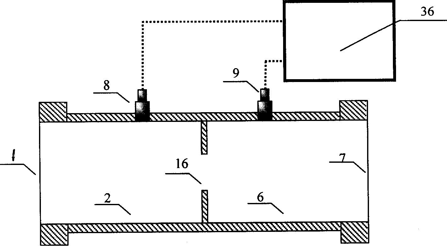
Embodiment approach 1

[0068] The configuration of Embodiment 1 can be used for flow detection of various single-phase fluids. The detection process is as follows: the first step is to carry out the calibration experiment of the flow detection device, and select several flow values ​​within its range to perform For real-flow calibration, under each flow condition, the output signals of the two dynamic pressure sensors are recorded continuously for 10 seconds. The second step is to carry out the calibration calculation work, first calculate the difference between the two signal records under each flow condition, and then calculate and store the spectral density value of the difference. Since the spectral density presents a monotonous increase trend with the increase of the flow rate, the relationship between the two can be obtained through nonlinear interpolation. The third step is to conduct on-site flow detection. At this time, it is only necessary to directly compare the spectral density obtained...

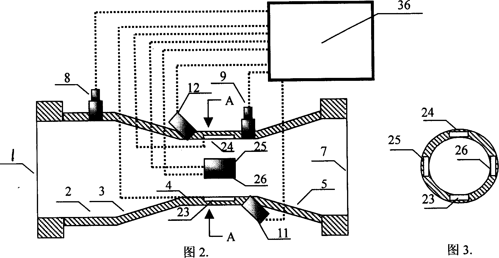
Embodiment approach 2

[0083] Embodiment 2 This configuration can be used for flow detection of various three-phase flows. For example, the three-phase flow of oil, gas and water commonly exists in the oil and gas industry. Since the output of most oil and gas wells often contains three components: crude oil, natural gas and mineralized water, the economical and effective on-line non-separation detection of the flow of each phase in the output of oil and gas wells is very important for reservoir management, production process optimization and production. Process monitoring and so on are of great significance. But so far this detection is basically realized by a separator, which has poor precision and low efficiency, and an automatic detection device that does not need to be separated is urgently needed. Embodiment 2 The process of using this configuration to detect oil-gas-water three-phase flow is as follows:

[0084] In the first step, representative parameters of the multiphase flow are defined...

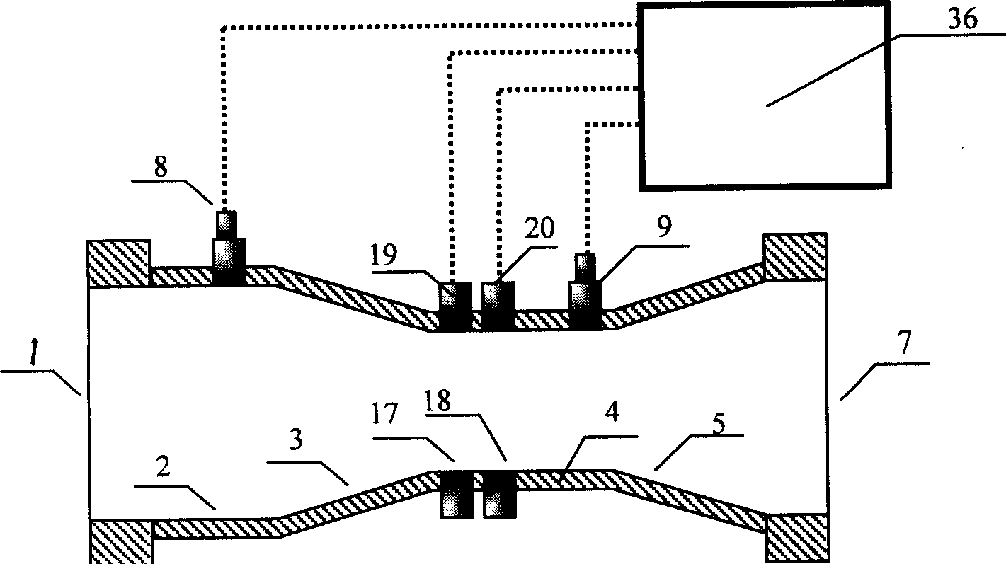
Embodiment approach 3

[0093] This configuration of Embodiment 3 can be used for flow rate and water content detection of water-carrying condensate gas and other two-phase flows containing moisture. Its detection process is similar to Embodiment 2.

[0094] Fig. 5 is a structural schematic diagram of Embodiment 4 of the present invention. It can be seen from the figure that the partial structure of this embodiment is completely the same as that of Embodiment 2, and the completely identical structure of this part will not be repeated here. The difference between the two implementations:

[0095] First of all, the throttling device can be made without insulating materials, the ultrasonic transducers 11, 12 near the inner surface of the throat 4 have changed their spatial positions, and an ultrasonic transducer 13 has been added, which is compatible with the ultrasonic transducer. The transducer 11 is directly coupled through the pipe wall, or directly coupled through other coupling materials, so as to ...


PUM


Abstract

The invention relates to a flow measuring device of a stream, which fixes at least two dynamic pressure sensors on the measuring path of the changing cross-sectional area used to measure the undulating quantity value of restricting differential pressure which can measure the stream flow. The device overcomes the traditional shortages and can measure multiply two-phase flow. When adding a phase measuring device on the invention, it can measure two-phase flow with much accuracy and can be used to measure oil, gas and water three-phase flow.

Description

technical field [0001] The present invention relates to a flow detection device based on pressure detection. More specifically, the present invention belongs to a device for flow detection by detecting the pressure fluctuation value generated by the throttling device, and when the fluid is various two-phase The device is particularly suitable for flow or three-phase flow. Background technique [0002] In real production and life, fluids are everywhere. The traditional throttling differential pressure flowmeter uses the throttling differential pressure characteristics of fluid flow to detect its flow characteristics. It has been successfully used in industry for more than a hundred years, and its global sales volume has long occupied the first place among all kinds of flow meters. , reaching more than 50% of the total amount of instruments. [0003] The throttle differential pressure flowmeter is based on the Bernoulli equation and the flow continuity equation. When the fl...

Claims


Application Information

Patent Timeline
Patent Type & Authority Applications(China)
IPC IPC(8): G01F1/34
CPCG01F1/363G01F1/66G01F1/74G01F1/666
Inventor 陈宇
Owner 陈宇
Why Eureka
Try Eureka