Low hysteresis bearing

a bearing and low hysteresis technology, applied in the field of low hysteresis bearings and control strategies, can solve the problems of increasing bearing starting and running torque, short bearing life, increasing raceway noise, etc., and achieves low hysteresis pivot, negligible residual hysteresis, and decoupling stiffness from hysteresis

Inactive Publication Date: 2011-04-07
FIRST PRINCIPALS
View PDF0 Cites 17 Cited by
  • Summary
  • Abstract
  • Description
  • Claims
  • Application Information

AI Technical Summary

Benefits of technology

The present invention is directed to a low hysteresis pivot bearing suitable for a variety of applications. The relationship between torque and angular displacement is substantially linear, with negligible residual hysteresis. The present pivot bearing also decouples stiffness from hysteresis, without increasing translation error.
In one embodiment, the intermediate member is not powered by a motor. Rather, the intermediate member is free to spin due to the rotation of the inner and outer ball bearings when torque is applied by the voice coil actuation. The constraints on the ball bearings are reduced, thus substantially reducing the hysteresis effects.
The relationship of torque applied to the pivot bearing to angular displacement of the pivot bearing is preferably substantially linear. A controller can be programmed to actuate the rotary actuator only during position critical displacement. The angular displacement of the intermediate member displaces the bearing to minimize formation of meniscus films of lubricant on the inner and outer sleeve bearings.

Problems solved by technology

If the pre-load P is too high, bearing life will be short, raceway noise will increase, and bearing starting and running torque will increase.
If the applied pre-load P is insufficient, corrosion can occur due to vibration causing the balls to resonate and abrade on the raceways.
Torque also has a direct effect upon temperature generation, speed variation, power consumption (at start-up and during running), and power consumption variations caused by unstable rotation.
Unfortunately, by the time the pivot bearing is driven out of its stick / slip starting torque state and into rotary movement, excessive driving current may have been applied to the voice coil motor, and the transducer head can be mis-positioned with respect to the desired track position.
This reduction in stiffness leads to increased run-out, particularly when the actuator assembly is exposed to vibrations emanating from short and long seeks and external vibrations.
Knife edge bearings have met with major cost, reliability and manufacturing drawbacks.
Knife edge designs do not resolve the intrinsic problem of elastic deformation between the knife edge and the supporting structure during micro-actuation.
The knife edge pivots also have very low stiffness leading to impractical translation modes of the suspension arm.

Method used


Image

  • Low hysteresis bearing
  • Low hysteresis bearing
  • Low hysteresis bearing

Examples


Embodiment Construction

The entire content of U.S. Provisional Application No. 61 / 180,854, filed May 23, 2009; 61 / 185,998, filed Jun. 11, 2009; and 61 / 187,135, filed Jun. 15, 2009 is hereby incorporated by reference.

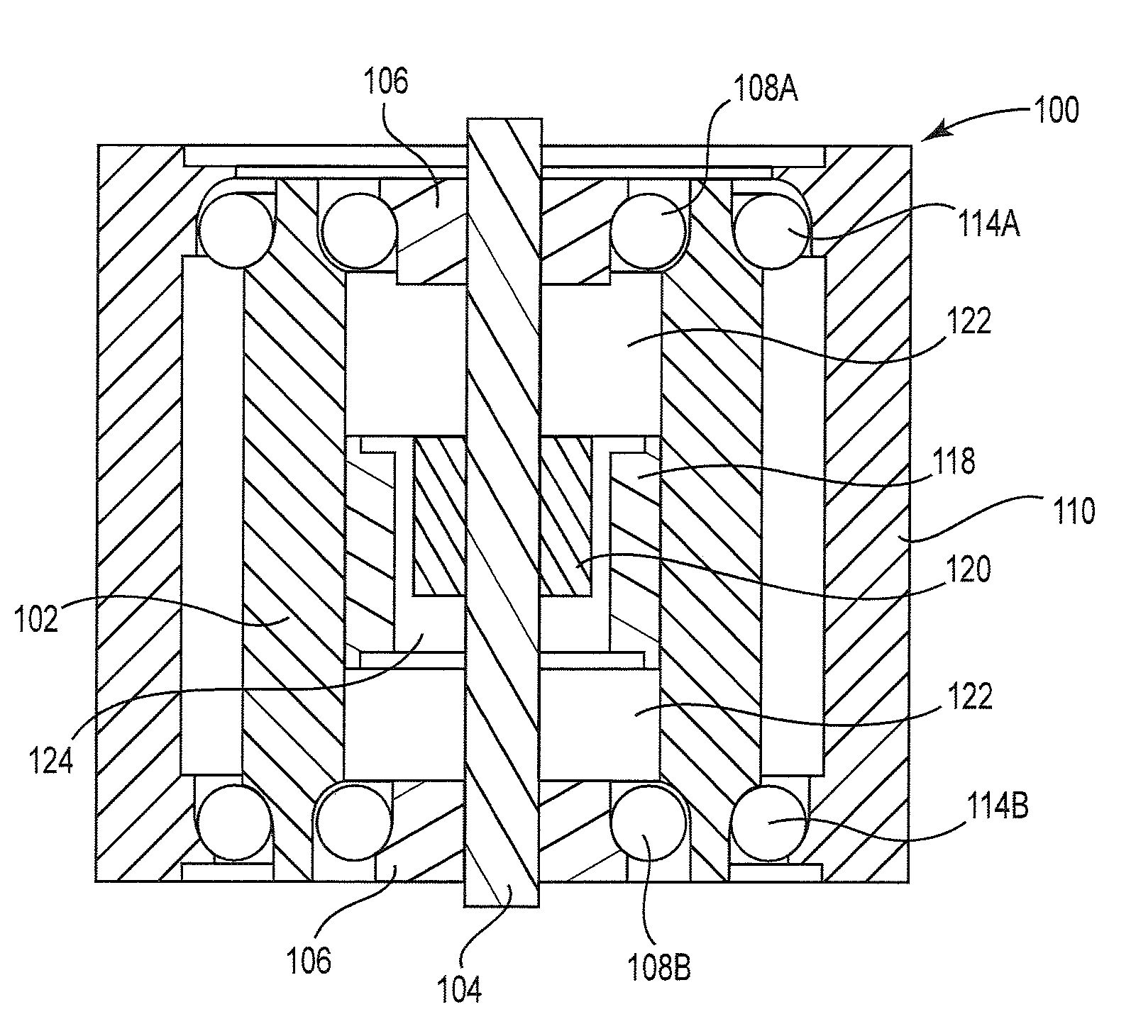
FIGS. 4 through 6 are various views of a pivot bearing 100 in accordance with an embodiment of the present invention. Intermediate member 102 is pivotally supported on stationary shaft 104 by intermediate member bearings 106. In the illustrated embodiment, the intermediate member bearings 106 include upper bearing set 108A and lower bearing set 108B (collectively “108”). Consequently, the intermediate member 102 can be angularly displaced concentrically around the stationary shaft 104. As will be discussed below, the intermediate member bearings 106 can be subjected to a substantial pre-load without creating excessive hysteresis. In an alternate embodiment, the intermediate member bearings 106 can be fixedly mounted to the intermediate member 102.

The present embodiment contemplates the intermed...


PUM

PropertyMeasurementUnit
rotationaaaaaaaaaa
torqueaaaaaaaaaa
position critical displacementaaaaaaaaaa

Abstract

A low hysteresis pivot bearing suitable for a variety of applications. The relationship between torque and angular displacement is substantially linear, with negligible residual hysteresis. The pivot bearing includes a stationary shaft and at least one intermediate member pivotally connected to the stationary shaft by an intermediate member bearing. At least one outer sleeve is pivotally connected to the intermediate member by an outer sleeve bearing. At least one rotary actuator angularly displaces the intermediate member relative to the stationary shaft.

Description

FIELD OF THE INVENTION The present invention relates to a low hysteresis bearing and control strategies suitable for a variety of applications, including as a pivot bearing for a rotary actuator within disk drives.BACKGROUND OF THE INVENTIONHard disk drives 30, such as illustrated in FIG. 1, employ rotary actuators 32 that position magnetic transducers 34 over selected information tracks on rotating magnetic disks 36. The transducers 34 are positioned with great accuracy by a closed-loop, servo system driven by voice coil motor (VCM) 38. The feedback in the control loop is provided by transducer 34 reading servo information pre-written on the magnetic disk 36.Rotatable housing 58 on pivot bearing 40 supports rotation of suspension arms 42 through arc 44. In most hard disk drives, the suspension arm 42 is actually a plurality of suspension anus supported by an E-block. (See for example FIG. 3 of U.S. Pat. No. 6,411,471). During track following or track-to-track seek operations, the r...

Claims


Application Information

Patent Timeline
Patent Type & Authority Applications(United States)
IPC IPC(8): G11B5/56F16C19/00
CPCF16C19/55F16C2370/12G11B5/5569G11B5/4813
Inventor BOUTAGHOU, ZINE-EDDINESCHWAPPACH, KARL G.
Owner FIRST PRINCIPALS
Why Eureka
Try Eureka