Fabricated gas turbine vane ring

a gas turbine and static vane technology, applied in the direction of machines/engines, stators, liquid fuel engines, etc., can solve the problems of difficult control of the fillet radius of the joint between the strut and the duct wall

Inactive Publication Date: 2011-04-07
PRATT & WHITNEY CANADA CORP
View PDF16 Cites 49 Cited by
  • Summary
  • Abstract
  • Description
  • Claims
  • Application Information

AI Technical Summary

Problems solved by technology

A sharp corner at the junction of the strut and the duct wall may be formed by such welds, which may result in difficulties controlling the fillet radius of the joint between the strut and the duct walls.
In addition, static vane rings made from sheet metal may present other engineering challenges such as thin walls which may compromise the vane from an aerodynamic and static structures / lifing standpoint.

Method used


Image

  • Fabricated gas turbine vane ring
  • Fabricated gas turbine vane ring
  • Fabricated gas turbine vane ring

Examples


Embodiment Construction

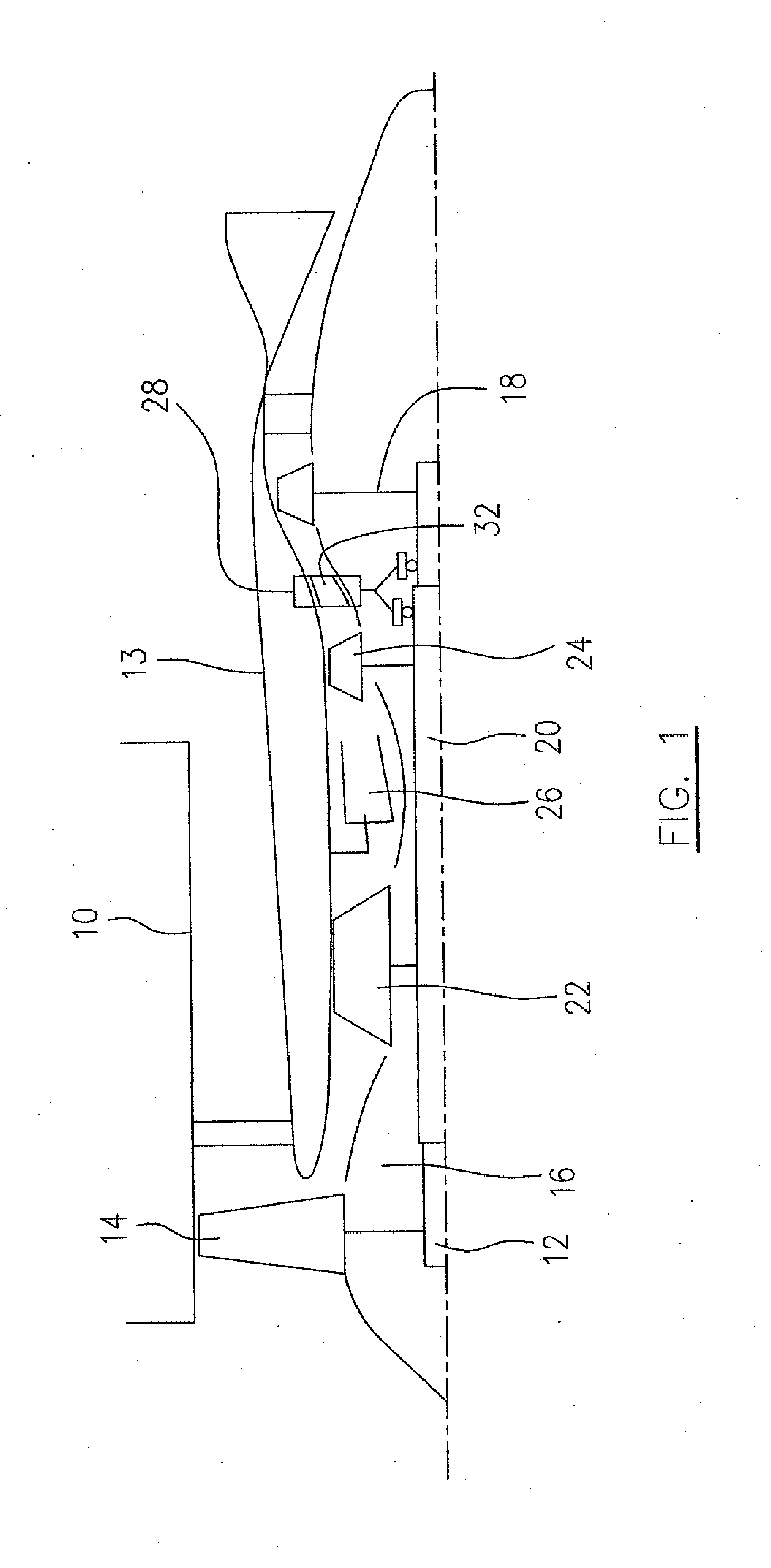
[0017]Referring to FIG. 1, a turbofan gas turbine engine includes a fan case 10, a core casing 13, a low pressure spool assembly (not numbered) which includes a fan assembly 14, a low pressure compressor assembly 16 and a low pressure turbine assembly 18 connected by a shaft 12, and a high pressure spool assembly (not numbered) which includes a high pressure compressor assembly 22 and a high pressure turbine assembly 24 connected by a turbine shaft 20. The core casing 13 surrounds the low and high pressure spool assemblies to define a main fluid path therethrough (not numbered). In the main fluid path there is provided a combustor 26 to generate combustion gases in order to power the high and low pressure assemblies 24, 18. A mid turbine frame 28 is disposed between the high and low pressure turbine assemblies 24 and 18 and includes an annular inter turbine duct (ITD) 32 therein for directing hot gases to pass therethrough from the high pressure turbine assembly 24 to the low pressu...


PUM


Abstract

A static vane ring for gas turbine engines includes a plurality of radial struts extending between and interconnecting outer and inner duct walls which define an annular duct therebetween. A load transfer apparatus is attached to at least one of the outer and inner duct walls to transfer load from vane to ring, and between vanes.

Description

TECHNICAL FIELD[0001]The described subject matter relates generally to gas turbine engines and more particularly, to a fabricated static vane ring used in a gas turbine engine.BACKGROUND OF THE ART[0002]A static vane ring generally includes a plurality of radial struts extending between and interconnecting outer and inner duct walls of the vane ring. In a fabricated sheet metal construction, at least the struts are made of sheet metal and connected by welding to the respective outer and inner duct walls. As schematically illustrated in FIGS. 8 and 9 an end of the strut is conventionally directly welded to the respective outer and inner duct walls of the vane ring. A sharp corner at the junction of the strut and the duct wall may be formed by such welds, which may result in difficulties controlling the fillet radius of the joint between the strut and the duct walls. In addition, static vane rings made from sheet metal may present other engineering challenges such as thin walls which ...

Claims


Application Information

Patent Timeline
Patent Type & Authority Applications(United States)
IPC IPC(8): F01D9/04
CPCF01D9/044F05D2230/237F05D2230/232
Inventor DUROCHER, ERICNGUYEN, LAM
Owner PRATT & WHITNEY CANADA CORP
Why Eureka
Try Eureka