Optimizing Utility Usage by Smart Monitoring

a smart monitoring and utility technology, applied in the field of system and method for optimizing utility usage, to prevent utility consumption device failure or regulation

Inactive Publication Date: 2011-04-07
SHINDE MAKARAND +2
View PDF18 Cites 177 Cited by
  • Summary
  • Abstract
  • Description
  • Claims
  • Application Information

AI Technical Summary

Benefits of technology

[0009]Another aspect of the invention is that each monitoring device in a network is assigned an automatic media access control (MAC) address or identifier (i.e., digital identifier) which is used by the regulation technique for polling each device for collecting measured data. By polling every device sequentially, the software manages to streamline data collection and not cause excessive noise on the communication network whose primary function might be to carry a utility such as power, water, gas, etc.
[0011]Another aspect of the invention is a data collection system on the same communication network and the display of utility usage summary for various utilities such as power, water and gas individually or combination thereof on the same computer user interface. Having one interface for multiple utilities could provide residential or enterprise user a common billing interface for multiple utility providers. A two-way communication between the monitoring device and the regulation technique would facilitate implementation of optimization techniques to improve uptime of the utility consuming devices and to reduce cost by minimizing waste of utility.
[0035]The method may comprise coupling a sensor to the monitoring device for sensing a surrounding condition of the monitoring device and transmitting sensing information from the sensor to the CPU. The method may also comprise processing the sensing information at the CPU and providing feedback to a user or another device. The feedback may comprise preventing utility consuming device failure or regulation. The method may further comprise using a closed loop communication system for monitoring and regulating the utility consuming device.

Problems solved by technology

However, due to large customer base and volume of data, solutions provided by utility providers have traditionally relied on data collected at the meter level.
However, such cumulative summary of usage does not flag points and / or times of excess usage of utilities to the consumer.

Method used


Image

  • Optimizing Utility Usage by Smart Monitoring
  • Optimizing Utility Usage by Smart Monitoring
  • Optimizing Utility Usage by Smart Monitoring

Examples


Embodiment Construction

General Overview

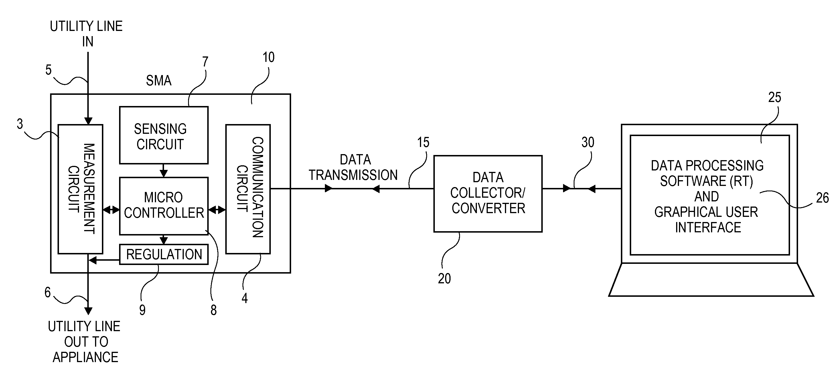
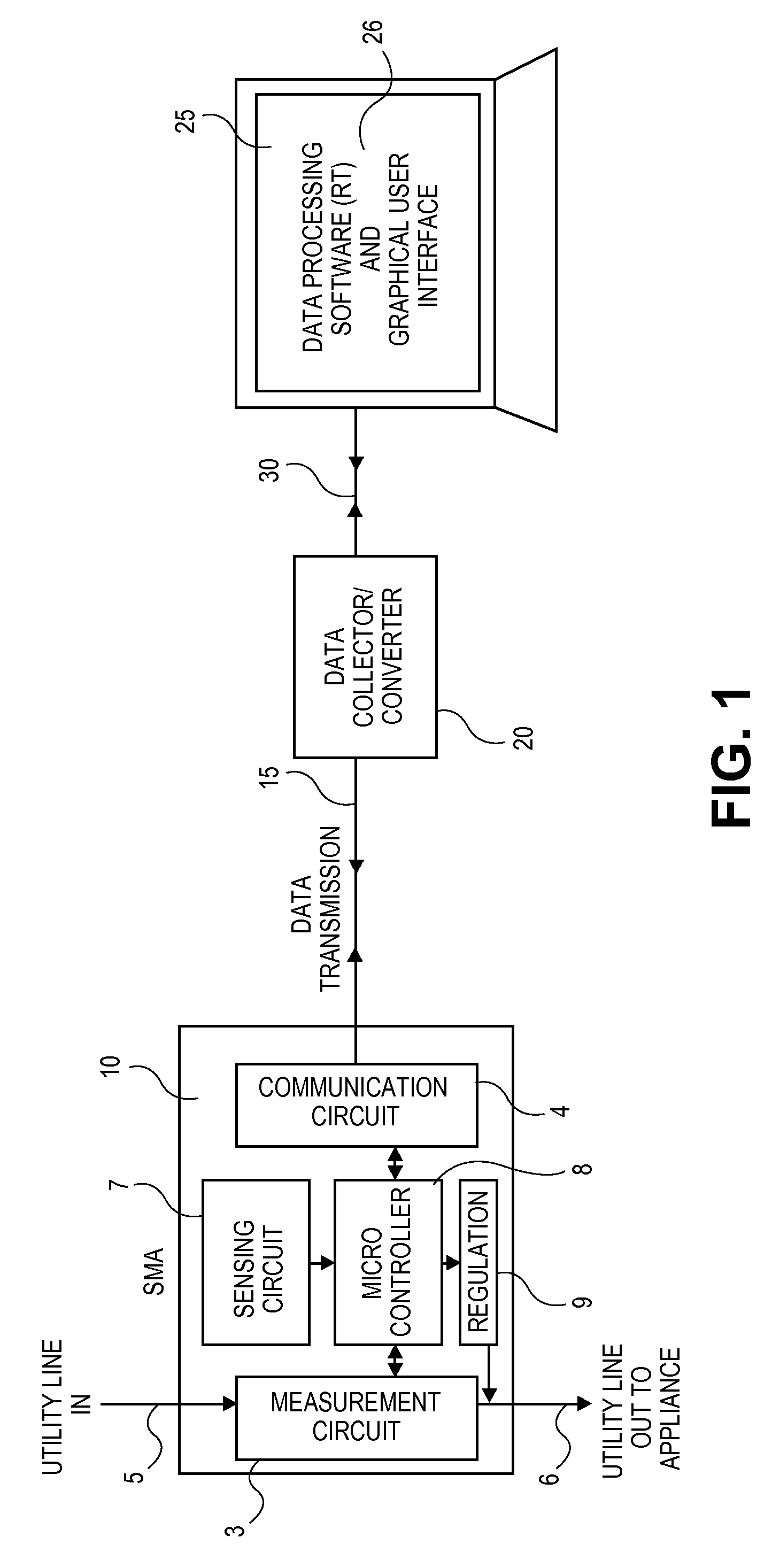
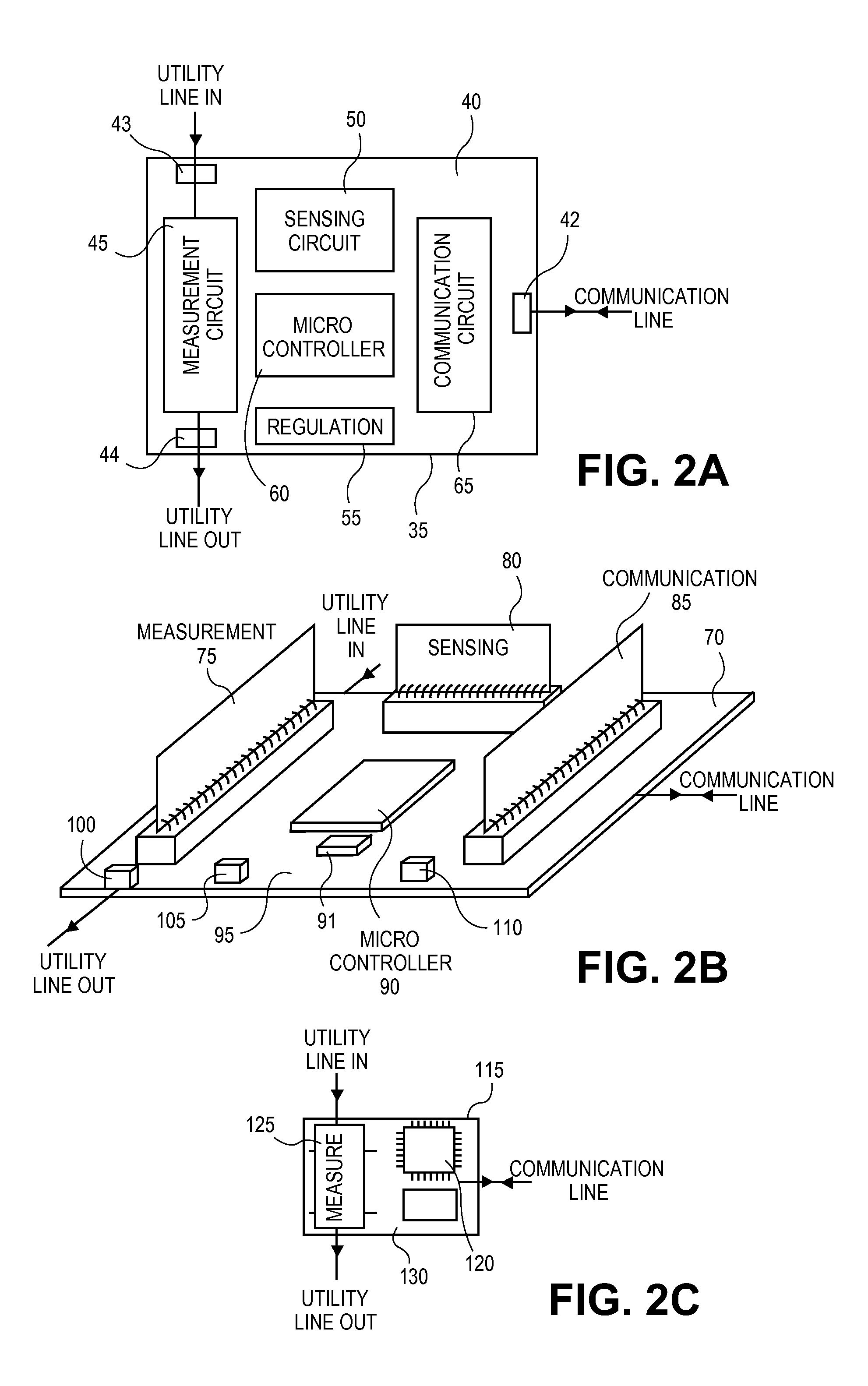
[0052]One aspect of the invention further relates to a system that helps consumers or enterprises track usage of utilities at a point of use. The system preferably comprises an apparatus and a regulation technique. In particular, a system setup comprises installation of an apparatus or multiple apparatuses at points inside a facility where the utility is used. Data collected by multiple apparatuses is carried over existing connections (i.e. wiring, power, telephone or ethernet) in a facility to a CPU or a host computer and processed by the regulation technique. Data collected in this fashion from multiple points of use over time can be modeled to produce a detailed view of how, where and when utilities are used. For example, data may also be modeled to provide a real-time update to a user, allow a user to create a target utility consumption, allow a user to create an event-based profile, and further allow priority sequencing of the utility consuming device in compari...


PUM


Abstract

A system for optimizing utility usage is described. The system comprises a monitoring device adapted to be connected to a utility point, a utility consuming device and a central processing unit (CPU). The monitoring device is configured to regulate utility usage information of the utility consuming device and is further configured to assign a unique identifier to the monitoring device. The monitoring device comprises a measurement circuit for measuring utility usage information, wherein the measurement circuit is coupled to the utility point. The monitoring device is configured to communicate with the CPU, wherein the monitoring device is configured to transmit utility usage information of the utility consuming device to the CPU on the unique identifier and wherein the monitoring device is configured to receive utility usage information of the utility consuming device and wherein the CPU is configured to process the utility usage information based on the unique identifier.

Description

CROSS-REFERENCE TO RELATED APPLICATIONS[0001]This application claims priority to U.S. Provisional Application No. 61 / 249,237, filed Oct. 6, 2009, entitled “Optimizing Residential, Commercial and Industrial Energy Usage by Smart Monitoring and Regulation of Consumption”, which is incorporated by reference herein.INCORPORATION BY REFERENCE[0002]All publications and patent applications mentioned in this specification are herein incorporated by reference to the same extent as if each individual publication or patent application was specifically and individually indicated to be incorporated by reference.FIELD OF THE INVENTION[0003]This invention generally relates systems and methods for optimizing utility usage.BACKGROUND OF THE INVENTION[0004]Power utility companies typically measure a customer's power consumption solely at the point at which the power enters the customer's building or unit. Measurements made at meter-level suits the needs of utility providers but not necessarily of a c...

Claims


Application Information

Patent Timeline
Patent Type & Authority Applications(United States)
IPC IPC(8): G06F1/28G01R21/00G06F19/00
CPCH02J13/0003Y04S20/18Y02B90/228H02J1/001H02J13/00004H02J1/002H02J13/00016H02J13/00036H02J1/14Y02B90/20Y04S20/00
Inventor SHINDE, MAKARANDBRISKO, WILLIAMSHINDE, NITU
Owner SHINDE MAKARAND
Why Eureka
Try Eureka