Vehicle suspension control system and method

Inactive Publication Date: 2011-04-07
GENERAL ELECTRIC CO
View PDF14 Cites 9 Cited by
  • Summary
  • Abstract
  • Description
  • Claims
  • Application Information

AI Technical Summary

Problems solved by technology

Under some operating conditions, while the commanded lift may be technically achievable, it may however adversely affect the locomotive truck or rail or other infrastructure.
For example, a lift commanded in the presence of wheel slip may lead to increased stress on the truck and axle of the slipping wheel, thereby reducing the useful life of the component and reducing the performance of the system.
Similarly, a lift commanded when the locomotive is o

Method used


Image

  • Vehicle suspension control system and method
  • Vehicle suspension control system and method
  • Vehicle suspension control system and method

Examples


Embodiment Construction

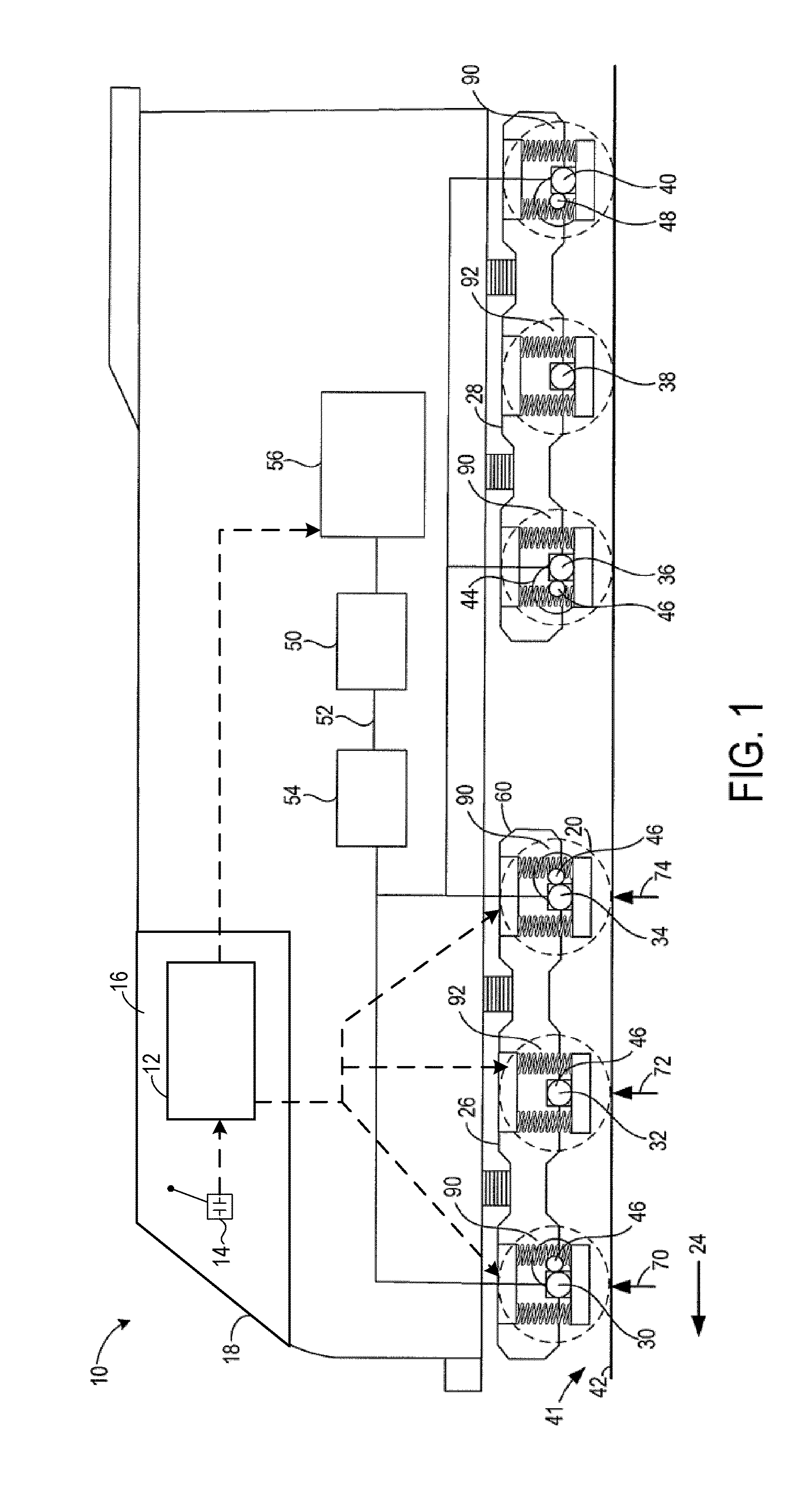
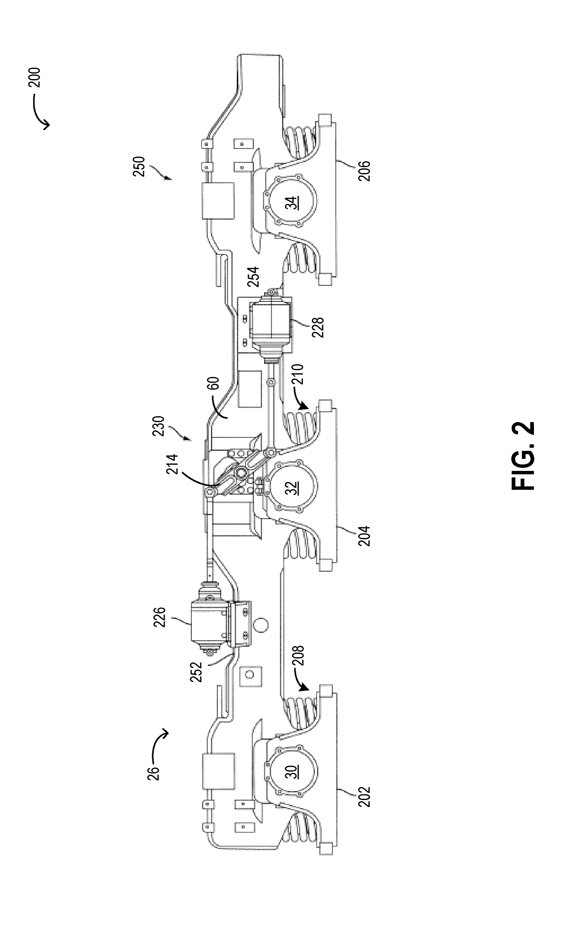
[0015]Vehicles, such as locomotives, may be configured with truck assemblies including lift mechanisms (such as, suspension systems) for transferring weight among wheels and / or axles supporting the locomotive. One example of such a mechanism is illustrated with reference to FIGS. 1-3. The mechanism enables dynamic weight management (DWM), that is, enables the weight (of the locomotive) on each truck to be selectively, and dynamically, redistributed among powered and un-powered axles responsive to vehicle and truck operating conditions. For example, during a “DWM lift”, such a mechanism permits a tractive force (from the locomotive on to the rail) to be increased by distributing a supported load from an un-powered to a powered axle when traction is desired. Likewise, during a “DWM de-lift”, such a mechanism permits the supported load to be more evenly distributed among the powered and un-powered axles when less traction is desired.

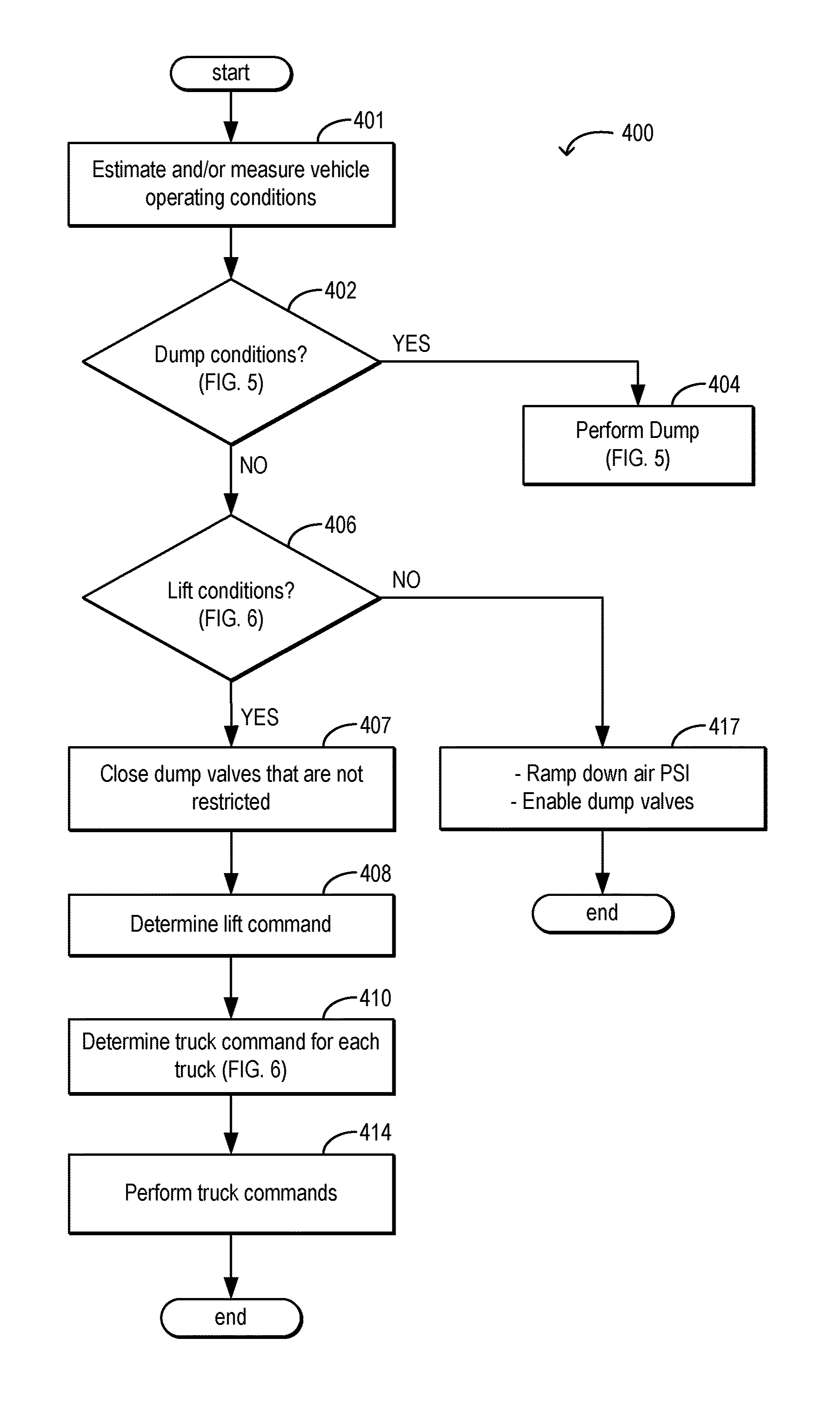
[0016]As illustrated with reference to FIG. 4, a vehi...


PUM


Abstract

Methods and systems are provided for controlling a vehicle having a first truck with a first lift mechanism and a second truck with a second lift mechanism, each of the first and second trucks further configured with a plurality of axles, each of the first and second lift mechanisms configured to dynamically transfer weight from one axle to another. In one embodiment, the method comprises, responding to an operating condition by adjusting the first lift mechanism different from the second lift mechanism.

Description

FIELD[0001]The subject matter disclosed herein relates to a method and system for controlling a lift mechanism in a vehicle.BACKGROUND[0002]Vehicles, such as diesel-electric locomotives, may be configured with truck assemblies including two trucks per assembly, and three axles per truck. The three axles may include at least one powered axle and at least one non-powered axle. The axles may be mounted to the truck via lift mechanisms (such as, suspension assemblies including one or more springs) for adjusting a distribution of locomotive weight (including a locomotive body weight and a locomotive truck weight) between the axles. Weight distribution among the powered and non-powered axles may be performed statically and / or dynamically by adjusting a lift command. Under some operating conditions, while the commanded lift may be technically achievable, it may however adversely affect the locomotive truck or rail or other infrastructure. For example, a lift commanded in the presence of wh...

Claims


Application Information

Patent Timeline
IPC IPC(8): B61F5/36G05D1/02
CPCB61F5/36B61C15/04
Inventor KUMAR, AJITH KUTTANNAIRWORDEN, BRETMCGARRY, JEREMY THOMAS
Owner GENERAL ELECTRIC CO
Why Eureka
Try Eureka