Method of optimizing the injection of a reactive fluid into a porous medium

a technology of reactive fluid and porous medium, applied in the field of methods, can solve the problems of large imprecisions within numerical simulations, no longer uniform concentration profile at the pore scale, and the availability of semi-analytical solutions

Inactive Publication Date: 2011-04-07
INST FR DU PETROLE
View PDF7 Cites 15 Cited by
  • Summary
  • Abstract
  • Description
  • Claims
  • Application Information

AI Technical Summary

Problems solved by technology

This is due to the fact that the concentration profile at the pore scale is no longer uniform.
Due to this fundamental interaction between the two scales, it appears that sizeable imprecisions within the numerical simulations can be obtained if the transport proportionality coefficients are badly assessed.
However, semi-analytical solutions are available only for basic geometries such as the circular cylinder or parallel plates.

Method used


Image

  • Method of optimizing the injection of a reactive fluid into a porous medium
  • Method of optimizing the injection of a reactive fluid into a porous medium
  • Method of optimizing the injection of a reactive fluid into a porous medium

Examples


Embodiment Construction

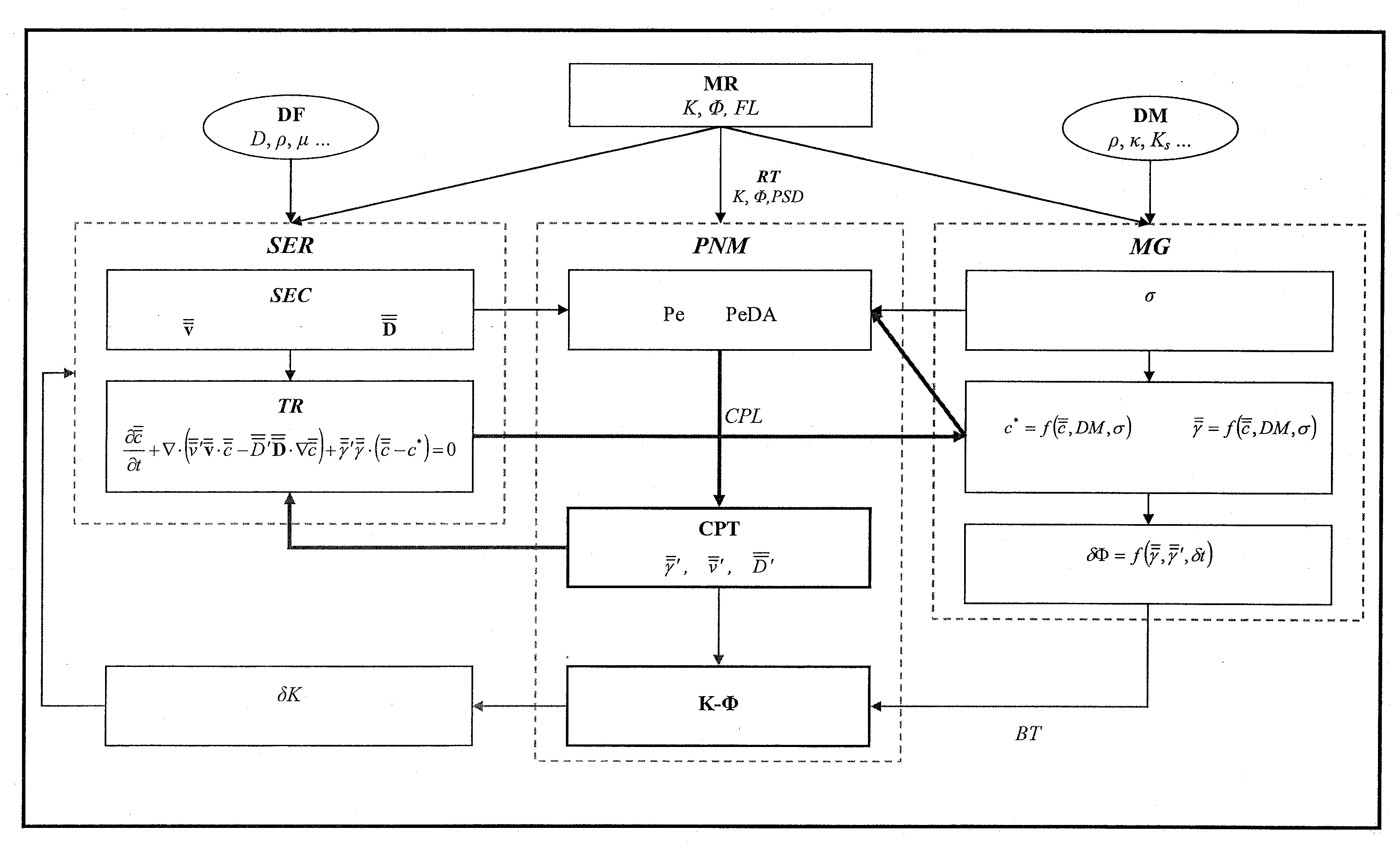
[0072]The invention relates to a method for developing an underground porous medium by injecting a fluid, notably a reactive fluid, therein. The method allows monitoring of the migration of the reactive fluid in the porous medium, by a simulation of the reactive transport of the reactive fluid within the medium.

[0073]According to an embodiment, the reactive fluid is CO2. It generally dissolves within the porous medium in liquid water or brine. Studying the migration of the CO2 injected amounts to studying the flow of the brine while accounting for the chemical reactions of the solute made up of CO2.

[0074]In this context, the method determines the CO2 concentration at any point of the medium. It is also possible to determine the concentration of other chemical species involved in a chemical reaction between the fluid and the medium, such as ions or molecules (CaCO3, Ca2+, CO2, CO32, . . . ).

[0075]The goal is to acquire data relative to the porous medium and to the reactive fluid (dis...


PUM


Abstract

The invention is a method of optimizing the injection of a fluid into a porous medium, using modelling the migration of the fluid within the medium having application for oil reservoir development. A reservoir model is constructed. In each cell of this the model, a PNM model representative of the pore network in the cell is constructed. The concentration of the fluid is then determined in each cell by solving the cell-scale reactive transport equation. Fluid concentration modifications at the level of the fluid / rock interface, at the pore scale, are therefore taken into account by means of the PNM models. Corrective coefficients for the reactive transport equation and a law between the permeability of the porous medium and the porosity of the porous medium are thus calculated. Finally, fluid injection is optimized as a function of the concentrations in each cell.

Description

BACKGROUND OF THE INVENTION[0001]1. Field of the Invention[0002]The present invention relates to the field of underground porous media development, and notably to the geological storage of carbon dioxide or enhanced hydrocarbon recovery through CO2 injection.[0003]2. Description of the Background Art[0004]Geological storage is considered for reducing the anthropic emission of carbon dioxide which is a greenhouse gas. Carbon dioxide gas is a reactive fluid within the porous medium. Its dissolution in water causes acidification thereof. This perturbation of the initial thermodynamic equilibrium causes a modification in the rock structure by dissolving and / or precipitating minerals. By thus changing the pore size distribution of the porous medium, the CO2 impacts the petrophysical properties of the rock, notably the porosity and the permeability. Other properties such as the capillary pressure and the relative permeabilities can also be affected. The wettability of the new mineral at t...

Claims


Application Information

Patent Timeline
IPC IPC(8): G06G7/58
CPCG06F17/5018Y02C10/14G06F2217/16G06F30/23G06F2111/10Y02C20/40
Inventor ALGIVE, LIONNELBEKRI, SAMIRVIZIKA, OLGA
Owner INST FR DU PETROLE
Why Eureka
Try Eureka