Wet compression apparatus and method

a technology of wet compression and apparatus, which is applied in the direction of machines/engines, liquid fuel engines, positive displacement liquid engines, etc., can solve the problems of affecting the spatial temperature distribution of downstream combustion, non-uniform fogging and water overspray, and degrading the desired downstream transverse temperature distribution. , to achieve the effect of reducing noise and reducing compression nois

Active Publication Date: 2012-09-11
VAST HLDG LLC
View PDF15 Cites 76 Cited by
  • Summary
  • Abstract
  • Description
  • Claims
  • Application Information

AI Technical Summary

Benefits of technology

[0011]Another embodiment of the present invention comprises a method of compressing and cooling a gaseous fluid distributed along a curvilinear stream wise flow through at least three compressor stages, comprising a rotor, or a stator and rotor. The method can comprise configuring an axial distribution of individual pressure ratios for the at least three compressor stages; configuring an axial distribution to deliver vaporizable cooling fluid; compressing the gaseous fluid; and delivering vaporizable cooling fluid into the gaseous fluid being compressed; such that evaporation of the vaporizable cooling fluid achieves at least a 50% degree of saturation of the gaseous fluid exiting the compressor stages.
[0012]Another embodiment of the present invention comprises a method of acoustic quieting of compressing gas with liquid to reduce compression noise by at least 2 dB relative to equivalent compression without liquid. In some embodiments, the method is characterized by a quieting fluid comprising a liquid is injected into the gaseous fluid through numerous orifices configured about one or more of: a stationary airfoil directing the gaseous fluid flow, a streamlined tube configured across the gaseous fluid flow; a rotary airfoil compressing the gaseous fluid flow; a duct wall constraining the gaseous fluid; further characterized in that, the noise is reduced in proportion to: the stage weighted mass flow ratio of unevaporated quieting fluid to gaseous fluid, relative equivalent gaseous fluid compression without the quieting fluid

Problems solved by technology

Relevant art fogging, overspray, and intercooling technology experience limitations in the amount of water evaporated and / or entrained into the compressor because of operational limitations within the compressor, such as surge, choke, and stall as well as concerns over blade erosion.
Non-uniform fogging and water overspray have been observed to impact downstream combustion spatial temperature distributions in axial turbines.
These in turn degrade the desired downstream transverse temperature distribution at the inlet of the turbine.
Such deviations from design can reduce turbine airfoil life and / or require lower mean temperatures that reduce system efficiency.

Method used


Image

  • Wet compression apparatus and method
  • Wet compression apparatus and method
  • Wet compression apparatus and method

Examples


Embodiment Construction

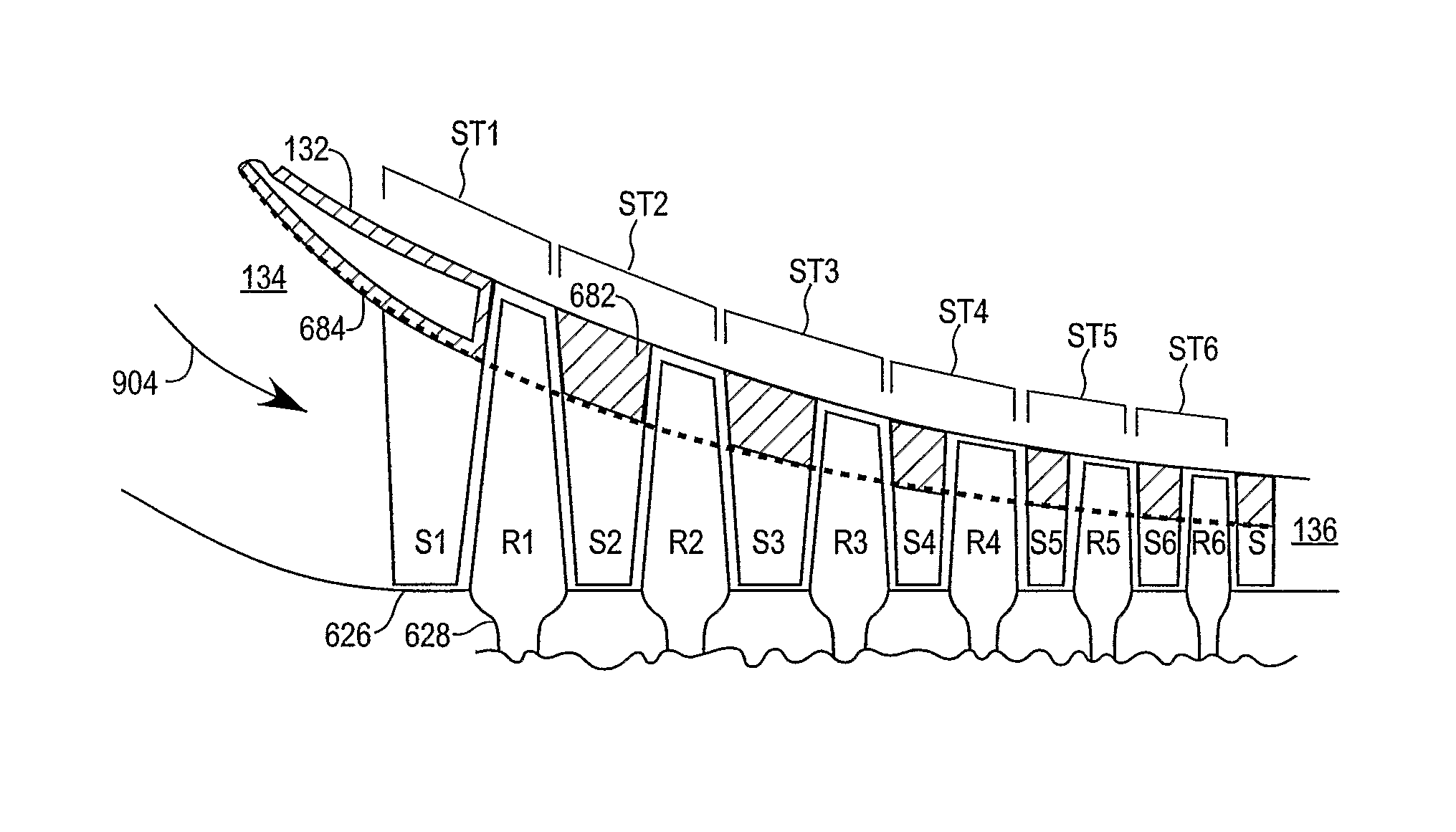
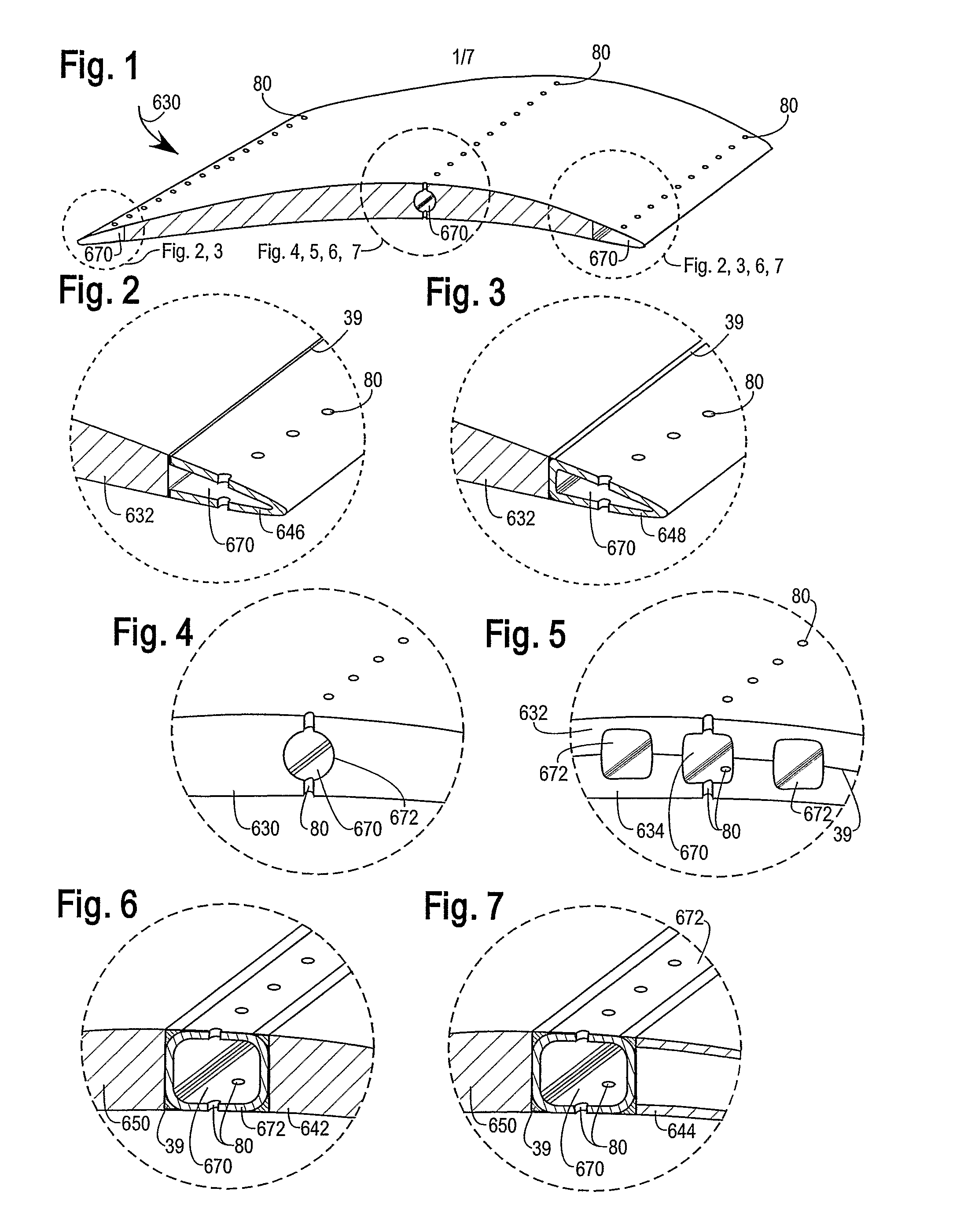
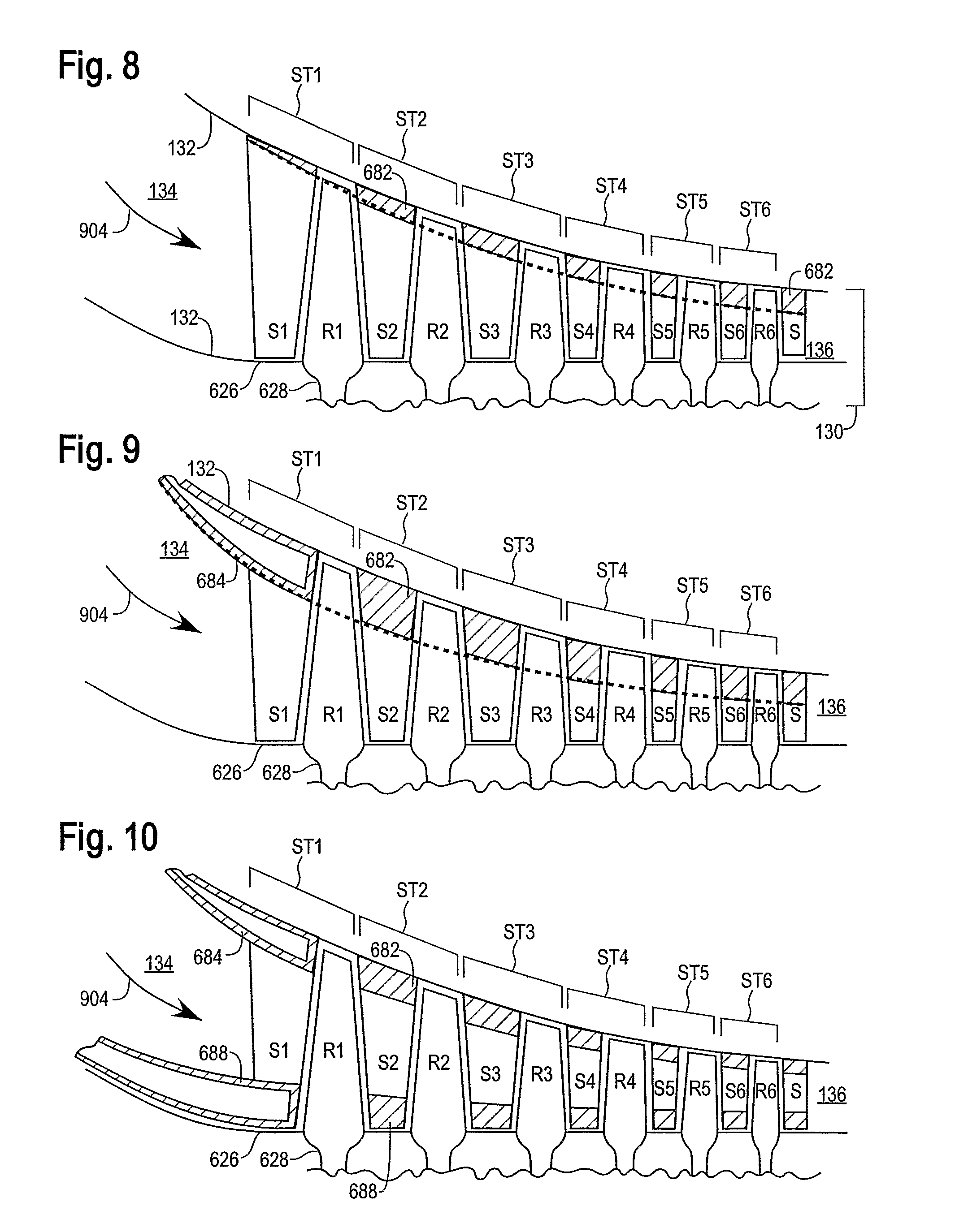
[0036]The invention discloses methods of “wet compression” or quasi or pseudo iso-thermal compression of gaseous fluid. i.e., for delivering a vaporizable liquid diluent into a gas or vapor containing fluid being compressed. e.g., spraying water into air that is being compressed in order to reduce the compression pumping work. The liquid diluent is primarily delivered through numerous orifices within a gas-containing fluid compressor to absorb heat from compression work. Some diluent is preferably entrained into the fluid entering the compressor. The diluent delivery transverse to the streamwise is preferably non-linear to account for the peaked gaseous fluid flow and differential residual drop entrainment due to evaporation.

Some Objects and Advantages of Selected Embodiments

[0037]Several objects and advantages of this invention are:

[0038]Cooling Compression:

[0039]To reduce the specific work of compressing a gaseous fluid;

[0040]To increase the net power producible by a compressed fl...


PUM


Abstract

This wet compression invention with a vaporizable fluid mist demonstrates major performance improvements over the relevant art in achieving a high degree of saturation, providing sensible cooling, strongly reducing the temperature increase due to compression work, reducing excess diluent air flow for downstream combustion, reducing compression noise, and increasing the achievable compressor pressure ratio. These improvements are obtained by one or more of: high mist or overspray from a) progressive axial injection of vaporizable fluid along the streamwise compression flow path, and b) transverse vaporizable fluid delivery from stators, rotors, perforated tubes, and / or duct walls, matching the gaseous fluid flow distribution across the compressor stream; c) reducing the compressor cross-sectional flow area of downstream compressor stages relative to up-stream stages, and d) increasing the rate of downstream vaporizable fluid injection relative to the rate of upstream injection, as a function of each compressor stage pressure ratio.

Description

PRIORITY INFORMATION[0001]This application is a claims priority under 35 U.S.C. §119(e) of U.S. Provisional Application No. 60 / 676,917 filed May 2, 2005, which is incorporated by reference herein.BACKGROUND OF THE INVENTION[0002]1. Field of the Invention[0003]The present invention relates to the fields of cooling gaseous fluids during compression and of diluted combustion.[0004]2. Description of the Related Art[0005]Conventional power systems experience major reductions in compressor capacity and net power with increasing ambient temperature, especially during summer peaking of demand. Some precooling or “fogging” of the intake air is being done upstream of the compressor. In relevant art, further water overspray has been used to entrain water droplets into the compressor intake to cool the air being compressed. Some systems provide intercooling between low and high pressure compressors using sprays of cooling liquid (or liquid diluent). Some relevant art uses flash evaporation and / ...

Claims


Application Information

Patent Timeline
Patent Type & Authority Patents(United States)
IPC IPC(8): F01D25/12
CPCF02C7/1435F04D29/542F04D29/5846F05D2260/212Y02T50/676Y02T50/60Y10T137/6416
Inventor HAGEN, DAVID L.
Owner VAST HLDG LLC
Why Eureka
Try Eureka