Locking hinge for an exterior vehicle mirror assembly

a technology for exterior vehicles and hinges, applied in door/window fittings, multi-purpose tools, construction, etc., can solve the problems of inability to adjust accurately, lack of flexibility in design, and large weight of locking hinges, so as to ensure the longevity of the spring element, enhance the locking position, and improve the effect of safety

Inactive Publication Date: 2011-04-14
LANG MEKRA NORTH AMERICA LLC +1
View PDF13 Cites 30 Cited by
  • Summary
  • Abstract
  • Description
  • Claims
  • Application Information

AI Technical Summary

Benefits of technology

[0014]Owing to the fact that the first axial spacing between the two bearing surfaces is less than the second axial spacing between them, the first and second locking surfaces are acted upon by the spring force inherent to the material of the first locking arm in the direction of the locking arrangement, with this spring force being superimposed on the first spring force. Thus, even if the spring element fails, for example, as a result of breakage of the spring or owing to general fatigue of the spring element caused by long-term sustained vibrations or similar, the second spring force is available as before, which then retains the locking position. Since this second spring force is not generated by a separate spring element, but, instead, by the inherent elasticity or spring action of the material used for the first locking arm, the separate spring element can be supported and relieved during normal operation of the locking hinge, and, hence, longer life of this spring element can be ensured. Further, in the event of failure of this spring element, there is a second spring action available, provided by the inherent property of the material used, which retains the locking position of the locking hinge.
[0015]It is preferable to provide a second locking element apart from the first locking element, which is primarily designed in the same manner as the first one. As a result of this, there is a symmetric distribution of forces, and, in particular, an enhancement of the locking position that can be achieved with the locking hinge between both the locking arms.
[0016]It is preferred to have the first locking arm designed in the form of two legs, which are connected directly or indirectly at one of their ends and have the bearing surfaces respectively with the first locking surfaces at both their free ends. The first locking arm can, thus, for example, be in the shape of a U or a V, whereby a mirror housing is placed at the connecting leg of the U or in the area of the tip of the V. The two free ends of the legs of the U or V with the bearing surfaces, on which the first locking surfaces are placed or formed, have a slight spacing between one another, which is less than the spacing of the second set of locking surfaces. Thus, the legs of the U or V must be expanded or stretched for the operation of the first and second locking elements, so that the free ends can be snapped on to the bearing block of the second locking arm, and thus, generate the second spring action. This enables assembly without the need for sophisticated tools, and with appropriate selection of the material and / or shape (length, geometry and cross-section of the legs) and the spacing or slight distance of both the legs, the spring force that can be achieved in this manner can be determined in advance and adjusted accurately.
[0017]In a preferred design variant, the bearing block on the second locking arm is cylindrical and the bearing surfaces lie on the front side of the cylinder. This particularly facilitates an aesthetically attractive design of the locking hinge.

Problems solved by technology

The disadvantage with this known type of locking hinge is that there is no flexibility whatsoever with respect to the design.
Moreover, such locking hinges are relatively big and are characterized by a large weight.
Finally, such locking hinges in the above mentioned rudimentary design are visually less attractive.
Locking hinges, especially for the exterior mirrors of utility vehicles are exposed to considerable stresses and loads in daily use.
Locking hinges with spring elements that operate as the retention force for holding the assembly together have the disadvantage that in the event of failure of the spring element, for example, breakage of the spring owing to the types of loads mentioned above, the locking hinge can lose its retaining feature or, at least, the retention or holding feature is impaired considerably.

Method used


Image

  • Locking hinge for an exterior vehicle mirror assembly
  • Locking hinge for an exterior vehicle mirror assembly
  • Locking hinge for an exterior vehicle mirror assembly

Examples


Embodiment Construction

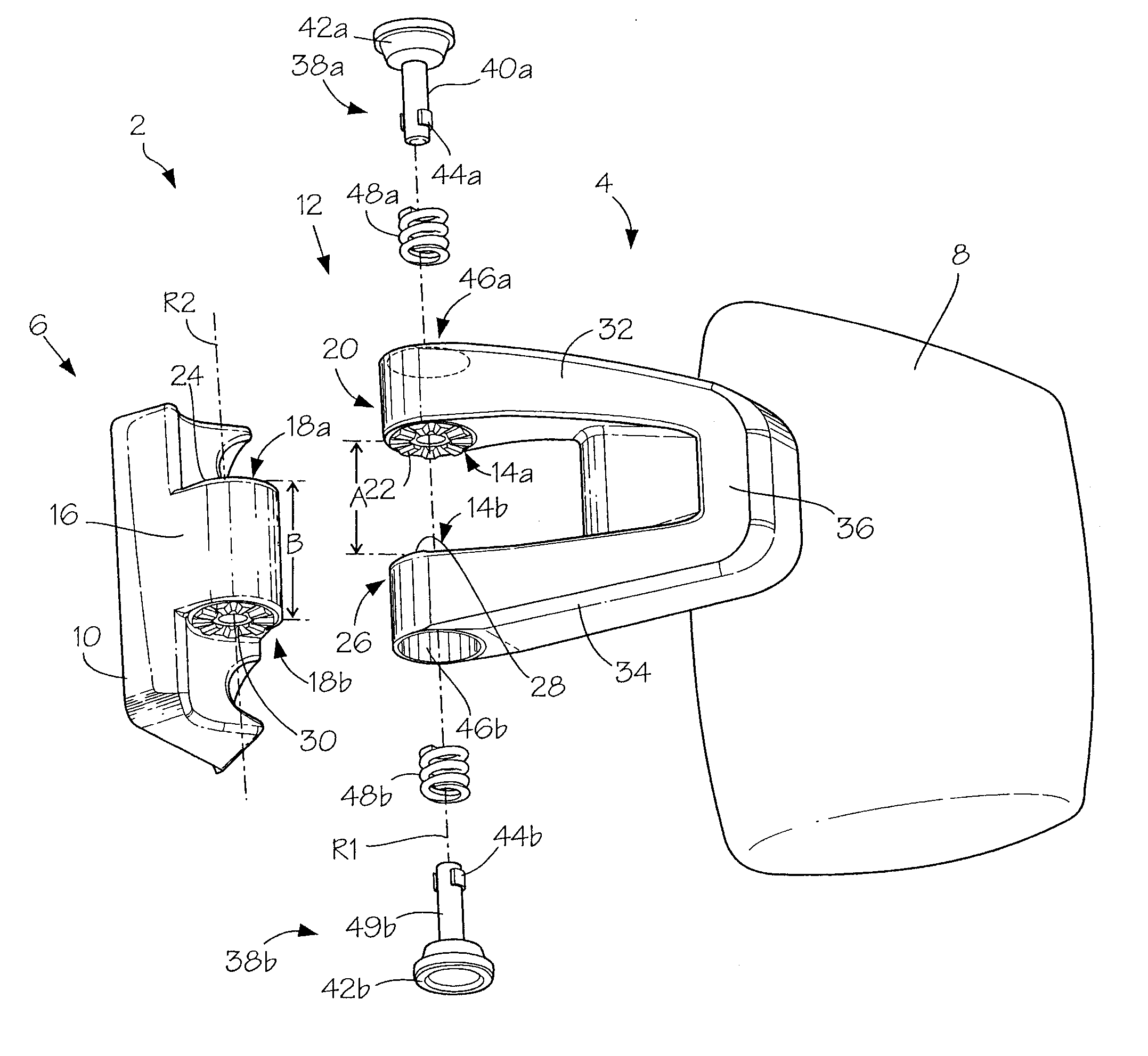
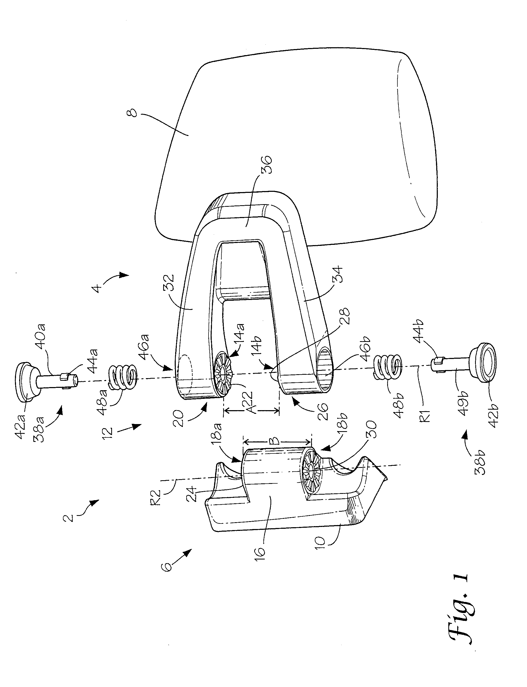
[0030]With reference to the drawings of FIGS. 1 and 2, the invention will now be described in more detail. The locking hinge, designated generally as 2, primarily consists of one first locking arm, 4, and one second locking arm, 6, whereby the first locking arm 4 serves to hold an exterior mirror head, 8, and the second locking arm, 6, is fixed to a vehicle body (not shown). For this purpose, the second locking arm, 6, has a base, 10, which can be screwed on to the body of the vehicle. The first locking arm, 4, and the second locking arm, 6, are pivoted to one another around a hinge axis, and can be fixed to one another in at least one relative position, which is represented in the disassembled drawing by two dotted lines, R1 and R2.

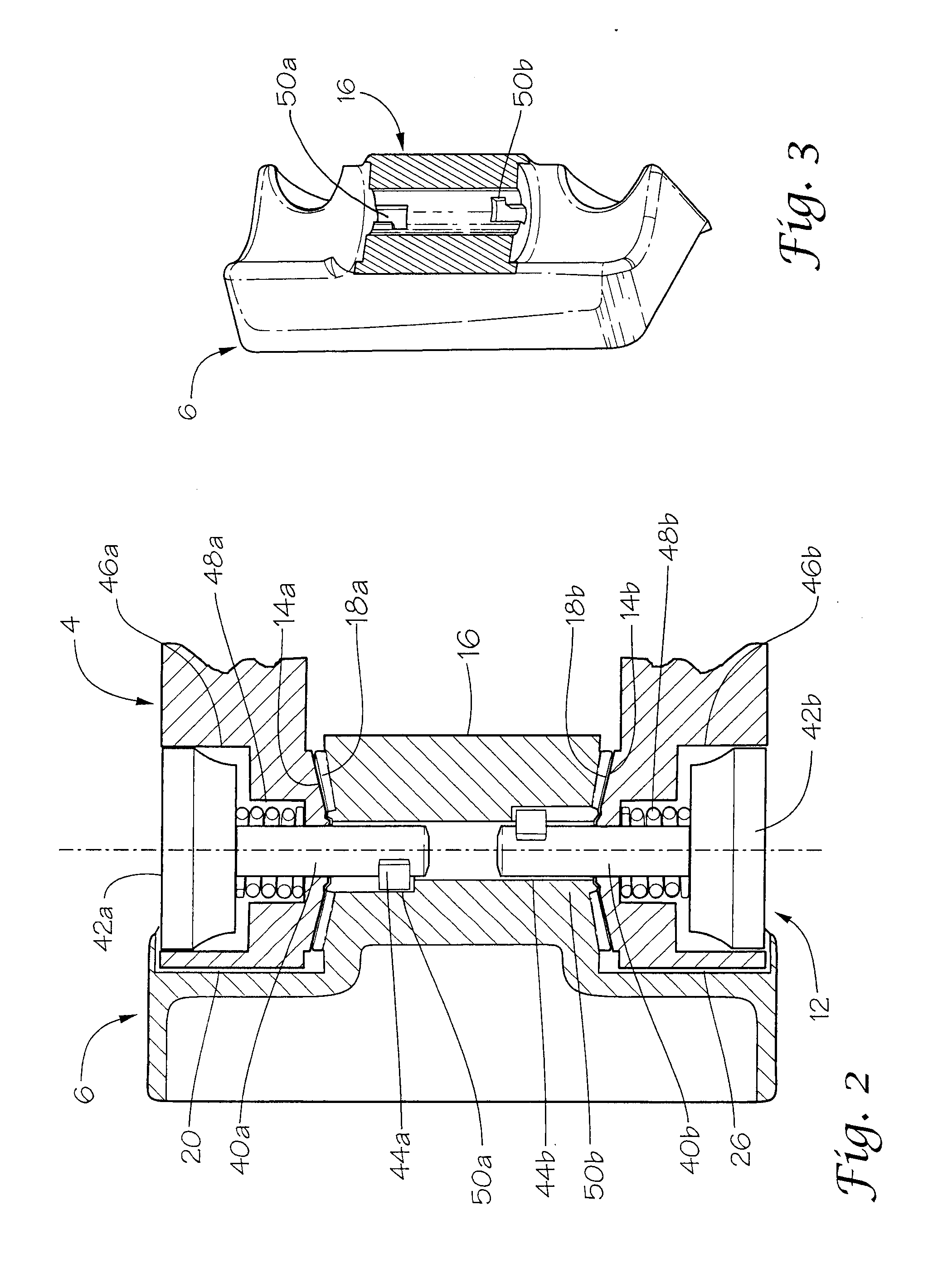
[0031]A hinge axis arrangement, designated generally as 12, is provided between the first locking arm, 4, and the second locking arm, 6, for this purpose.

[0032]The first locking arm, 4, has two bearing surfaces, 14a and 14b for the hinge axis arrangement...


PUM


Abstract

A first locking arm connected to a second locking arm on a locking hinge axis. A pair of bearing surfaces on the first locking arm have a first axial spacing, and the second locking arm having a bearing block carrying bearing counter surfaces engaging the bearing surfaces providing a hinged connection between the locking arms. The bearing counter surfaces having a second axial spacing. A first locking element having a first locking surface affixed on one of the bearing surfaces, and a second locking surface affixed on one of the bearing counter surfaces engaging the first locking surface. A spring element biasing the first and the second locking surfaces together. The first axial spacing is less than the second axial spacing so that there is a second spring force acting on the first and second locking surfaces superimposed on the first spring force.

Description

BACKGROUND OF THE INVENTION[0001]1) Field of the Invention[0002]The present invention relates to a locking hinge, and more particularly, to an exterior vehicle mirror assembly having a locking hinge for positioning a mirror head on pivotally connected support arms.[0003]2) Description of Related Art[0004]Locking hinges are used in diverse forms for the hinged fixture of rearview mirrors in automobiles. In the simplest form, such a locking hinge contains one first and one second locking arm that end in cooperating, generally identical, locking members. The locking members have cylindrical locking surfaces that face each other and both the locking arms or locking members are pressed and braced against each other with the help of a screw with a spring that goes through both of them.[0005]The disadvantage with this known type of locking hinge is that there is no flexibility whatsoever with respect to the design. Moreover, such locking hinges are relatively big and are characterized by a...

Claims


Application Information

Patent Timeline
Patent Type & Authority Applications(United States)
IPC IPC(8): E05D11/10
CPCB60R1/06B60R1/076Y10T16/5402Y10T16/540255Y10T16/54028
Inventor HEGER, SEBASTIANPFANZ, JURGENLANG, WERNER
Owner LANG MEKRA NORTH AMERICA LLC
Why Eureka
Try Eureka