Electric machine and power supply system having battery pack
Active Publication Date: 2011-04-14
PANASONIC INTELLECTUAL PROPERTY MANAGEMENT CO LTD
View PDF13 Cites 76 Cited by
Summary
Abstract
Description
Claims
Application Information
AI Technical Summary
This helps you quickly interpret patents by identifying the three key elements:
Problems solved by technology
Method used
Benefits of technology
Benefits of technology
[0012]The present invention has been made in order to solve the above problems, and provides an electric machine including a battery pack and a power supply system such that electric power can be transferred therebetween in a non-contact manner through a magnetic coupling between antennas, thus enabling safe and easy battery replacement. Moreover, the present invention also enables efficient electric power transfer even when there is a long distance between antennas, as compared with a conventional wireless power transfer method using electromagnetic induction.
[0016]According to an electric machine of the present invention, it is possible, without lowering the transfer efficiency, to supply electric power to a battery pack and to output electric power from a battery pack in a non-contact manner and with no contact points, thus enabling safe and easy battery replacement. Moreover, according to a power supply system of the present invention, it is possible to transfer energy efficiently to not only an electric machine but also a household electric appliance.
Problems solved by technology
In addition to the large amount of time required for charging, there is another problem that the power battery 72 deteriorates when fast-charged repeatedly.
With this method, however, it is not possible to realize efficient transfer when there is a long distance between the power-transmitting antenna and the power-receiving antenna, or when the antennas are not well aligned with each other.
Moreover, it is necessary to establish an electric path by fitting together connecter terminals, and the connecter fitting operation requires a relatively large force.
On the other hand, with a technique for transmitting power to a household electric appliance by an electromagnetic induction method, it is not possible to realize efficient transfer when there is a long distance between the power-transmitting antenna and the power-receiving antenna, or when the antennas are not well aligned with each other.
Method used
Image
Click on the blue label to locate the original text in one second.
Reading with bidirectional positioning of images and text.
Examples
embodiment 1
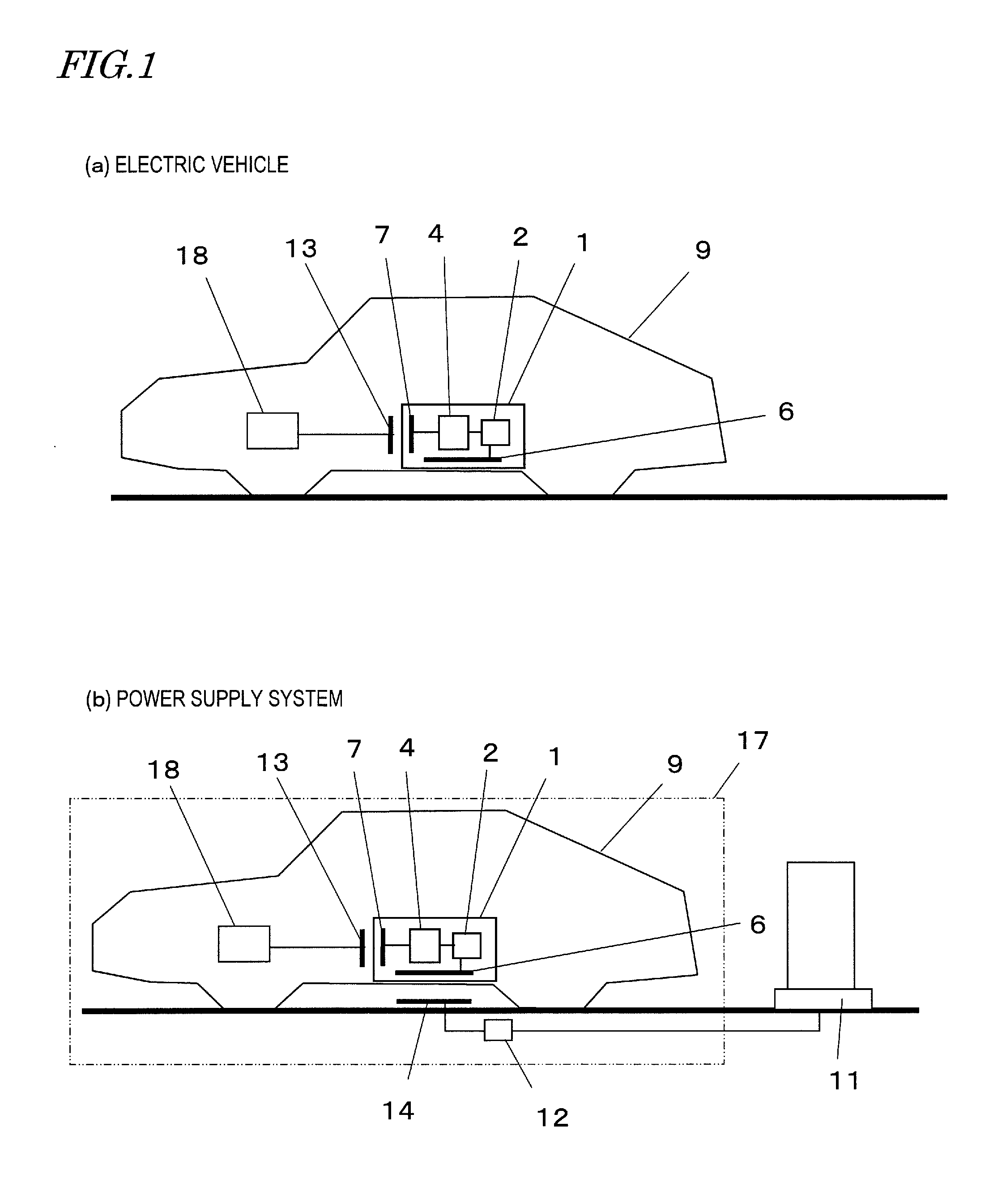
[0033]First, referring to FIG. 1, the first embodiment of the present invention will be described.
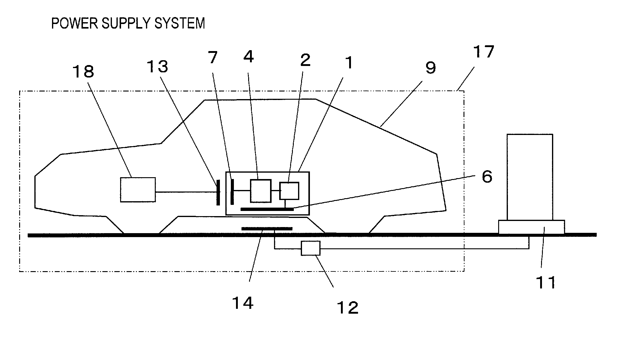
[0034]The present embodiment is directed to an electric vehicle, as an example of an electric machine having a battery pack of the present invention. FIG. 1(a) shows a configuration of the electric vehicle of the present embodiment, and FIG. 1(b) shows a configuration of a power supply system used in the electric vehicle. Note that the configuration of the electric vehicle and the power supply system shown in FIG. 1 is merely one example of possible configurations of the present embodiment, and the configuration of the present embodiment is not limited to that shown in FIG. 1.
[0035]An electric vehicle 9 shown in FIG. 1 runs using a driving electric motor 18 as the power source. The driving electric motor 18 serves as the power source of the electric vehicle 9 by receiving the electric power from a secondary battery 2 installed in the electric vehicle 9. In a preferred example, the secon...
embodiment 2
[0081]Referring now to FIG. 9, a second embodiment of the present invention will be described.
[0082]The electric vehicle 9 shown in FIG. 9 includes a seat 134 and a plurality of wheels so that a passenger 132 can be seated as shown in the figure. The battery pack holding section 54 holds the battery pack 1 so that the primary surface of the first antenna 6 is placed parallel to the ground, and the primary surface of the second antenna 7 is placed vertical to the ground. The primary surface of the fourth antenna 14 is placed parallel to the primary surface of the first antenna 6, and the primary surface of the third antenna 13 is placed parallel to the primary surface of the second antenna 7. Note that only one wheel is illustrated in FIG. 9, but the electric vehicle 9 of the present embodiment has four wheels. These wheels are driven by the driving electric motor 18.
[0083]The battery pack 1 is placed so that the distance from the seat 134 to the second antenna 7 is longer than the d...
embodiment 3
[0088]Referring now to FIGS. 10 and 11, a third embodiment of the present invention will be described.
[0089]FIG. 10 shows a basic configuration of an electric vehicle of the present embodiment. FIG. 11 shows an equivalent circuit diagram of the electric vehicle of the present embodiment. A main difference between the present embodiment and Embodiment 1 is that the electric vehicle of the present embodiment includes a second secondary battery 52 that is different from the secondary battery 2 in the battery pack 1.
[0090]As shown in FIG. 10, the electric vehicle includes the second secondary battery 52 which is a driving battery that can be charged / discharged, and a charge-discharge control section 51 which is a circuit for controlling the charging / discharging of the second secondary battery 52. The capacity of the secondary battery 2 is set so that the battery pack 1 is light enough to be carried around by a person, and a carry handle 53 is provided.
[0091]With the electric vehicle of ...
PUM
Abstract
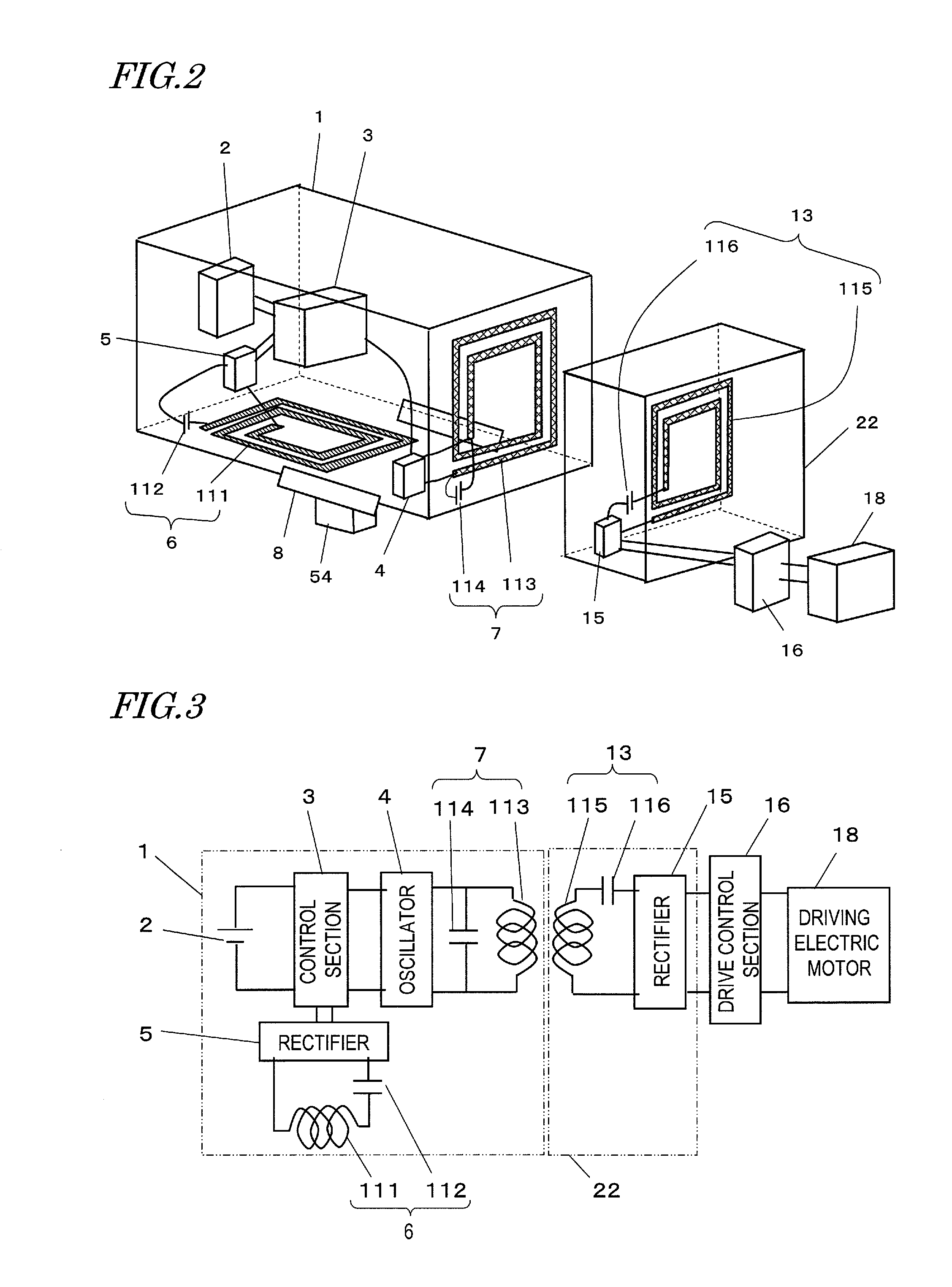
An electric machine and a power supply system, in which a battery pack can be easily and safely replaced with another, and electric power can be transferred with high transfer efficiency. An electric machine of the present invention includes a driving electric motor, a battery pack for supplying electric power to the driving electric motor, and an energy transfer section for transferring electric energy output from the battery pack to the driving electric motor. The battery pack includes a first antenna for receiving electric power from a power supply source located outside the electric machine by coupling with a first resonant magnetic field generated by the power supply source, at least one secondary battery charged by the electric power received by the first antenna, an oscillator for producing radio-frequency power by DC power discharged from the secondary battery, and a second antenna for generating a second resonant magnetic field by the radio-frequency power. The energy transfer section includes a third antenna that couples with the second resonant magnetic field generated by the second antenna, and transfers the radio-frequency power received by the third antenna to the driving electric motor.
Description
[0001]This application claims priority under 35 USC §119(e) to U.S. Provisional Application No. 61 / 251,425 filed on Oct. 14, 2009, the entire contents of which are incorporated herein by reference.BACKGROUND OF THE INVENTION[0002]1. Field of the Invention[0003]The present invention relates to an electric machine and a power supply system having a battery pack for wirelessly transferring electric power through a coupling by a resonant magnetic field.[0004]2. Description of the Related Art[0005]An electric machine such as an electric vehicle is driven by an electric motor. For example, an electric vehicle runs by using an electric motor as the power source, as opposed to a car whose power source is an internal-combustion engine. An electric vehicle has a power battery installed therein, and gains driving force by transferring energy stored in a power battery to the electric motor. The power battery may be, for example, a secondary battery such as a lithium-ion battery, a nickel hydrog...
Claims
Application Information
Patent Timeline
Application Date:The date an application was filed.
Publication Date:The date a patent or application was officially published.
First Publication Date:The earliest publication date of a patent with the same application number.
Issue Date:Publication date of the patent grant document.
PCT Entry Date:The Entry date of PCT National Phase.
Estimated Expiry Date:The statutory expiry date of a patent right according to the Patent Law, and it is the longest term of protection that the patent right can achieve without the termination of the patent right due to other reasons(Term extension factor has been taken into account ).
Invalid Date:Actual expiry date is based on effective date or publication date of legal transaction data of invalid patent.

