Ring light fundus camera

a fundus camera and ring light technology, applied in the field of ophthalmological examination instruments, can solve the problems of complex illumination optical path of a classical fundus camera, demanding production, and complicated structure of the entire optical system with its two separate optical paths, and achieve special, simple optical paths

Inactive Publication Date: 2011-04-14
CARL ZEISS MEDITEC AG
View PDF19 Cites 14 Cited by
  • Summary
  • Abstract
  • Description
  • Claims
  • Application Information

AI Technical Summary

Benefits of technology

[0004]An object of the present invention is to provide a simple fundus camera that has a special and simple optical path. All reflections such as the cornea reflection and the ophthalmoscope lens reflection are deflected in such directions that they do not interfere with the viewing optical path.

Problems solved by technology

The illuminating optical path of a classical fundus camera is complex.
A drawback is the complicated structure of the entire optical system with its two separate optical paths.
Its production is demanding and it is complicated and difficult to align.

Method used


Image

  • Ring light fundus camera
  • Ring light fundus camera
  • Ring light fundus camera

Examples


Embodiment Construction

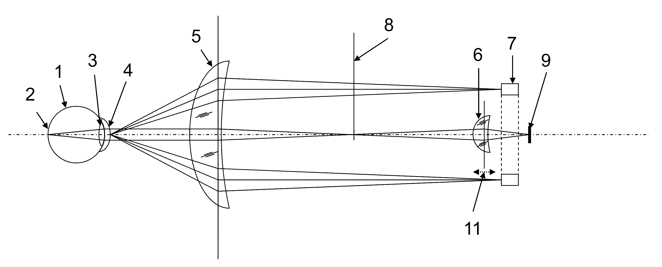
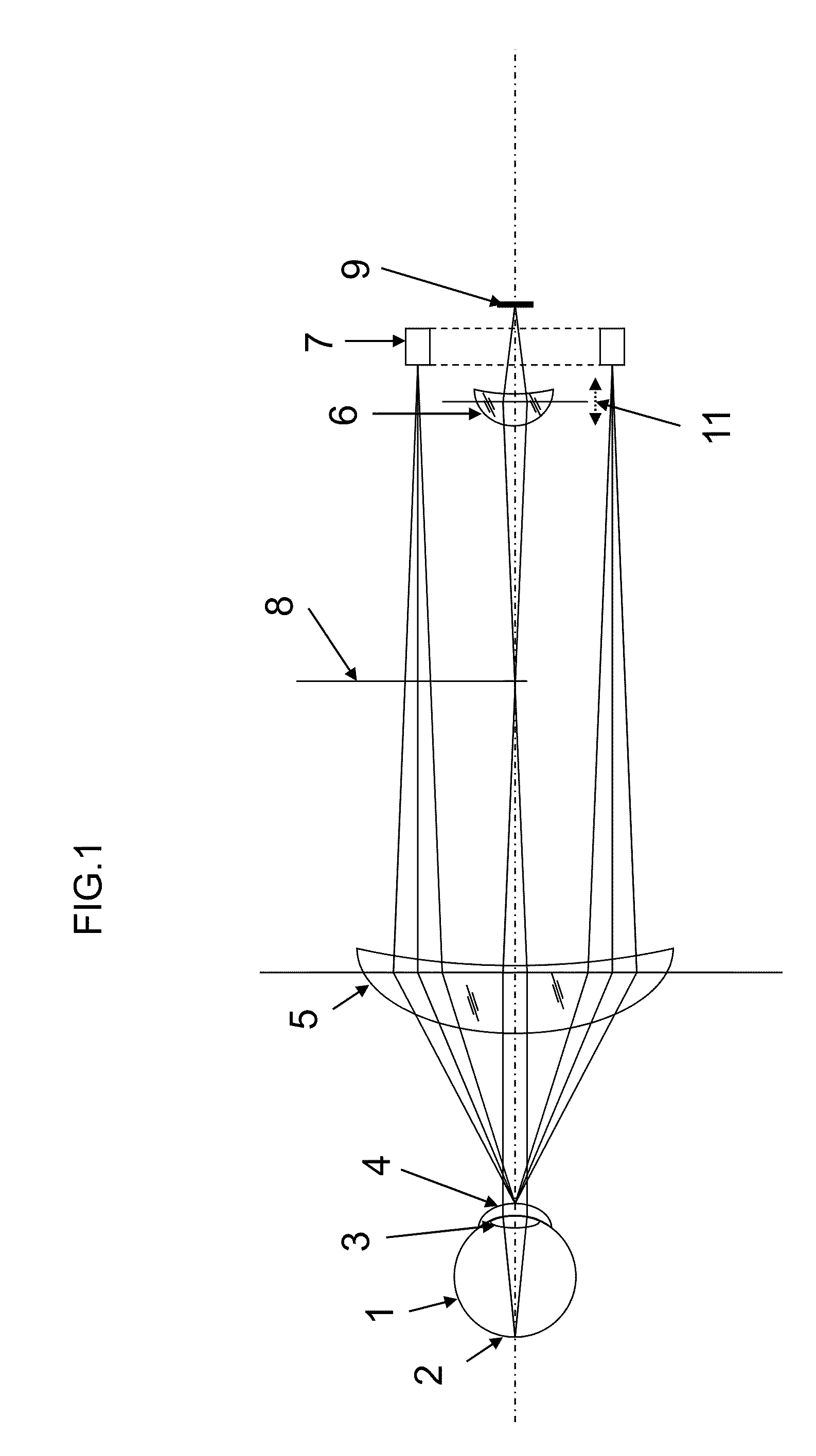
[0019]FIG. 1 shows a ophthalmoscope with a solid state camera. The illumination system is the ring light source 7. The viewing optical path includes a solid state surface sensor 9 located in the imaging plane and having a viewing optical system 6 positioned in front of it. The viewing optical path and the illuminating optical path are on one optical axis, the ophthalmoscope lens 5 being shared. The light emitted by the ring light source 7 is assumed to be approximately parallel. The ring light is projected through the ophthalmoscope lens 5 onto the cornea 4 of the patient's eye 1. The ring light projected on the cornea 4 scatters light into the inside of the eye 1. The retina 2 constitutes an illuminated object. The eye lens 3 images the retina 2 into infinity and the ophthalmoscope lens 5 focuses it in an intermediate image plane 8. A viewing optical system 6, which in the simplest case comprises an imaging device including an objective with a solid state surface sensor 9, is neede...


PUM


Abstract

A fundus camera includes a viewing optical path, an imaging device, and an illuminating optical path including at least one LED and a pinhole mirror reflecting the at least one LED into the imaging device, wherein at least a portion of the illuminating optical path shares an optical axis with at least a portion of the viewing optical path, and wherein the at least one LED includes a plurality of LEDs disposed in a shape of a ring.

Description

CROSS REFERENCE TO PRIOR APPLICATIONS[0001]This is a divisional application of U.S. application Ser. No. 11 / 459,487, filed Jul. 24, 2006, which claims priority to U.S. provisional Patent Application No. 60 / 702,038, filed on Jul. 22, 2005. The entire disclosure of both documents is incorporated by reference herein.FIELD[0002]The present invention relates to an ophthalmological examination instrument for photographing the fundus of the eye of humans and animals. Furthermore, front sections of the eye can be captured.BACKGROUND[0003]This ophthalmological examination instrument is also called a fundus camera. The classic structure of a fundus camera consists of a viewing optical path and an illuminating optical path. In the simplest case, the viewing optical path has two lenses. The image scale is essentially determined by the factor of the two focal lengths of the lenses. On the imaging side of the optical system, the fundus of the eye can be photographed or viewed through imaging devi...

Claims


Application Information

Patent Timeline
Patent Type & Authority Applications(United States)
IPC IPC(8): A61B3/12A61B3/14
CPCA61B3/12
Inventor KLEEN, WERNERSPERLING, WOLFGANG
Owner CARL ZEISS MEDITEC AG
Why Eureka
Try Eureka