A Semiconductor Laser

a semiconductor laser and laser technology, applied in semiconductor lasers, instruments, optical elements, etc., can solve the problems of reducing the rate of finished products, adversely affecting the quality of finished products, and high processing costs, so as to improve the efficiency and reliability of lasers, reduce the thickness of substrates, and reduce the effect of thermal dissipation

Active Publication Date: 2018-02-01
BWT BEIJING
View PDF1 Cites 8 Cited by
  • Summary
  • Abstract
  • Description
  • Claims
  • Application Information

AI Technical Summary

Benefits of technology

[0003]In view of the above problems, an object of the present invention is to provide a semiconductor laser. The semiconductor laser has characteristics of compact structure and simple optical path.
[0012]The semiconductor laser of the present invention has the following advantages and beneficial effects:
[0013]1. According to the present invention, because the multiple lasers are located in a same horizontal plane, the thickness of the substrate can be effectively reduced and the thermal dissipation capacity of the laser can be improved, so that the efficiency and reliability of the laser are improved.
[0014]2. According to the present invention, because the multiple lasers are located and mounted in a same horizontal plane, the structure of the substrate is greatly simplified and the difficulty of the processing is reduced, which can greatly reduce the mechanical material cost.
[0015]3. According to the present invention, because the multiple lasers are located and mounted in a same horizontal plane, steps between the light beams in the direction of the fast axis are produced by the reflecting mirrors with a specific tilt angle, then change of the spacing of the light beams in the direction of the fast axis can be easily achieved by adjusting the angle of the reflecting mirror so as to fit for semiconductor lasers with different characteristics. The versatility of the mechanical materials are thus increased and the cost of the management and production are greatly reduced.
[0016]4. The present invention relates to a steering compression optical system and this system can be either a transmission method or a reflection method. A steering compression system employing the transmission method is comprised of steering mirrors and a transmission wedge prism such as a rectangular wedge prism; and a steering compression system using the reflection method is comprised of steering mirrors and an optical element with a reflective surface having a specific tilt angle such as a right angle inclined reflective prism. This allows two adjacent laser beams to have a greater spacing when passing through the reflecting mirror, reduce the difficulty of the adjustment of the step spacing and increase the rate of the finished products.

Problems solved by technology

This method is of high requirement of precision of the step spacing processing, and of strict requirement of parallelism between the steps, therefore of relatively high processing cost.
Due to the existence of machining tolerance, it caused negative influence to the assembly and adjustment of an optical element is greatly and adversely effected and the rate of finished products is reduced.

Method used


Image

  • A Semiconductor Laser
  • A Semiconductor Laser
  • A Semiconductor Laser

Examples


embodiment 1

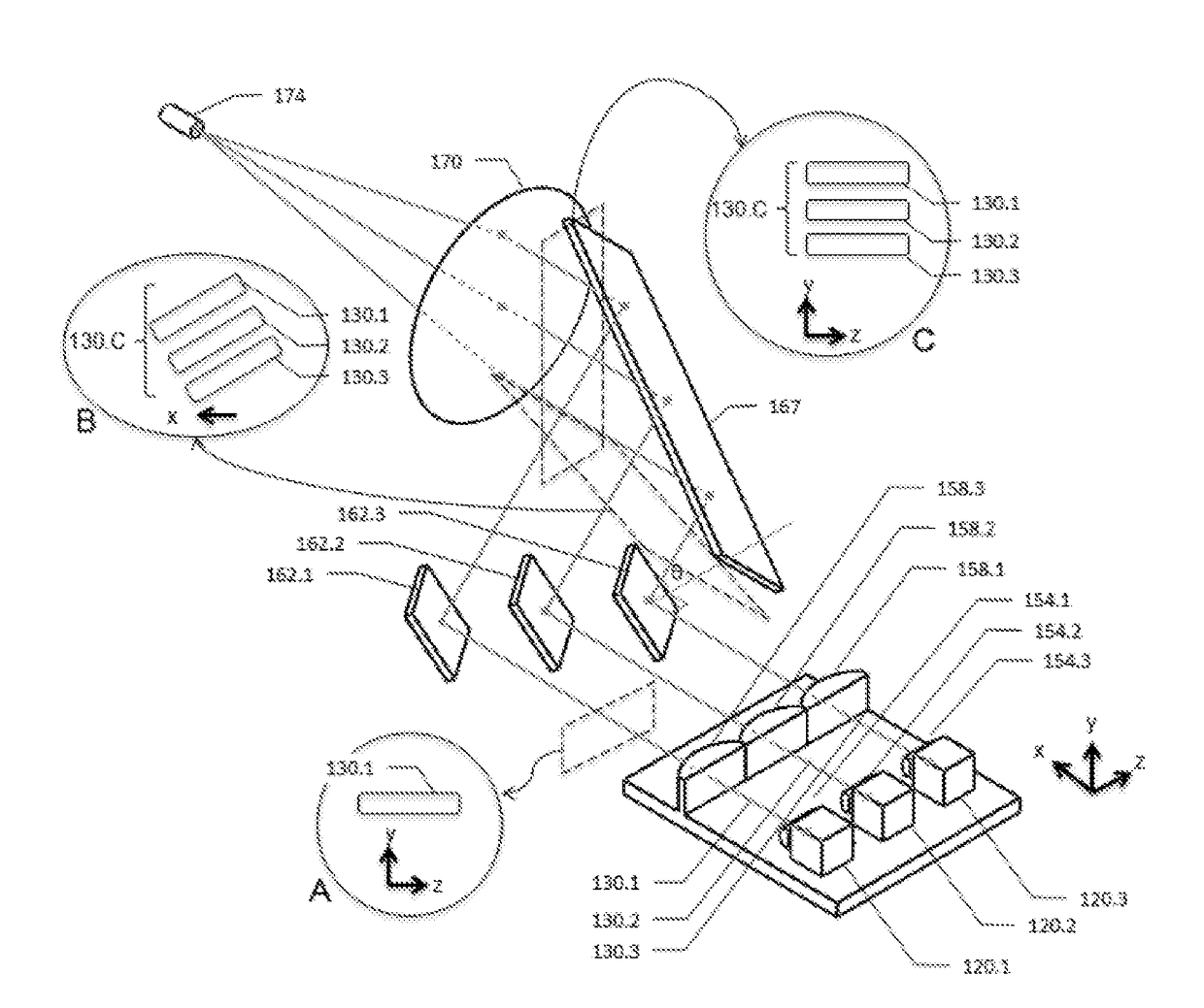
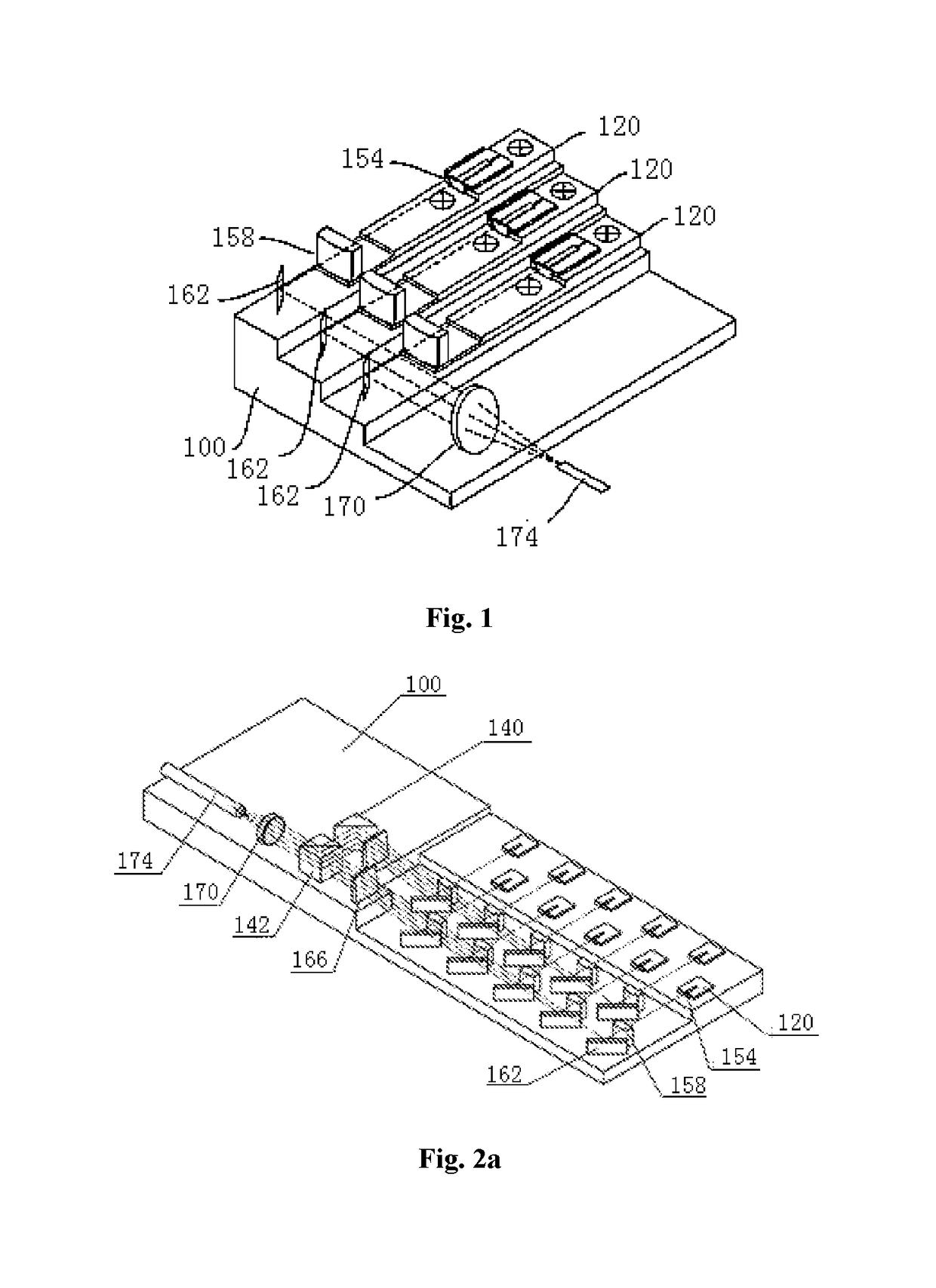
[0046]The present invention relates to a fiber-coupled laser, as shown in FIG. 2a-2c, including a substrate 100, two rows of lasers 120, a plurality of fast axis collimation components 154, a plurality of slow axis collimation components 158, a plurality of steering mirrors 162, a steering rectangular wedge prism 166, a steering prism 140, a polarization beam combination prism 142, a focusing lens 170 and a coupling optical fiber 174. The steering compression optical systems are the combinations of the steering mirrors 162 with the steering rectangular wedge prism 166. The laser beams outputted by the plurality of lasers 120, after being collimated and combined, are coupled into the optical fiber 174, and then outputted.

[0047]In the present embodiment, the substrate 100 is made of a material of high thermal conductivity such as oxygen-free copper. As shown in FIG. 2a-2c, there are three planes of different heights on the substrate 100 which are respectively used for carrying the las...

embodiment 2

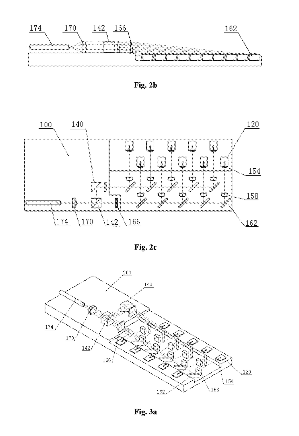
[0049]The structure of the present embodiment is substantially the same as that of the Embodiment 1, except that the two rows of LDs are relatively crossed and welded at two opposite sides of the substrate 200 and all of the LDs are located in the same horizontal plane, as shown in FIG. 3a-3c.

embodiment 3

[0050]Two rows of lasers 120 are located in different planes, each row of emitters is located in the same horizontal plane, and there is a specific spacing d2 in heights between two rows. The steering compression optical systems are formed by the combinations of the steering mirrors 162 and a rhombic prism 135. The rhombic prism 135 lifts the beams emitted by the lower row of lasers 120, ensuring that the two beams of laser, after being steered and compressed, have the same height when arriving at the polarization beam combination prism 142, as shown in FIG. 4a-4c.


PUM


Abstract

The present invention belongs to the field of laser technology, particularly relates to a semiconductor laser, including a substrate, and lasers, fast axis collimation components, slow axis collimation components, steering compression optical systems, a polarization beam combination prism, a focusing lens and an optical fiber provided on the substrate, wherein the lasers can be arranged in two rows or one row. And lasers of the same row are all located in a same plane. Each laser is sequentially provided with a fast axis collimation component and a slow axis collimation component in the direction of an optical path. The lasers of the same row correspond to a group of steering compression optical systems used to steer and compress the light beams collimated by the fast axis collimation components and the slow axis collimation components. The polarization beam combination prism is used for combining two beams of lasers having been steered and compressed by two groups of the steering compression optical systems. And the laser combined by the polarization beam combination prism is coupled into the optical fiber by the focusing lens. The present invention has a compact structure and a simple optical path, effectively reduces the thickness of the substrate and improves the thermal dissipation capacity of the laser, so that the efficiency and reliability of the laser are improved.

Description

TECHNICAL FIELD[0001]The present invention belongs to the field of laser technology, particularly relates to a semiconductor laser.DESCRIPTION OF RELATED ART[0002]Currently, the beam combiner of most of multiple single-emitter semiconductor lasers adopts a stepped structure, in which a substrate is processed to include steps equally spaced and on each of the steps a laser diode chip is mounted, as shown in FIG. 1. This method is of high requirement of precision of the step spacing processing, and of strict requirement of parallelism between the steps, therefore of relatively high processing cost. In the meanwhile, each step has a different thermal dissipation capacity due to the existence of height difference. When increasing the number of single-emitter diode lasers to increase the output power, it is necessary to compress the step spacing. Due to the existence of machining tolerance, it caused negative influence to the assembly and adjustment of an optical element is greatly and a...

Claims


Application Information

Patent Timeline
Patent Type & Authority Applications(United States)
IPC IPC(8): G02B27/10H01S5/40H01S5/00
CPCG02B27/10H01S5/0071H01S5/40H01S5/02476H01S5/06G02B19/0057G02B19/0019G02B27/0905G02B27/0911G02B27/0922H01S5/4012H01S5/4025H01S5/405G02B6/4206G02B6/4214
Inventor JIANG, XIAOCHENWANG, TIEGUO, WEIRONGWANG, BAOHUALIU, RUIXU, LEI
Owner BWT BEIJING
Why Eureka
Try Eureka