Method of speckle size and distribution control and the optical system using the same

Inactive Publication Date: 2008-07-24
LEAHSIN TECH
View PDF6 Cites 7 Cited by
  • Summary
  • Abstract
  • Description
  • Claims
  • Application Information

AI Technical Summary

Benefits of technology

[0033]Recently, laser speckle effect had been vastly used in the studies relating to surface roughness, imaging system adjustment and imaging quality evaluation, and so forth. With respect to the aforesaid basic characteristics of speckle, representing by its light intensity distribution, contrast, and characteristic size, the present invention is intended to provide a method of speckle size and distribution control and the optical system using the same. Preferably, the optical system is arranged inside a housing of a computer mouse that is primarily composed of a laser unit, a lens set, an image sensing unit and a digital signal processing unit. A laser mouse is an advanced optical mouse, which is capable of emitting a coherent light so as to detect more 
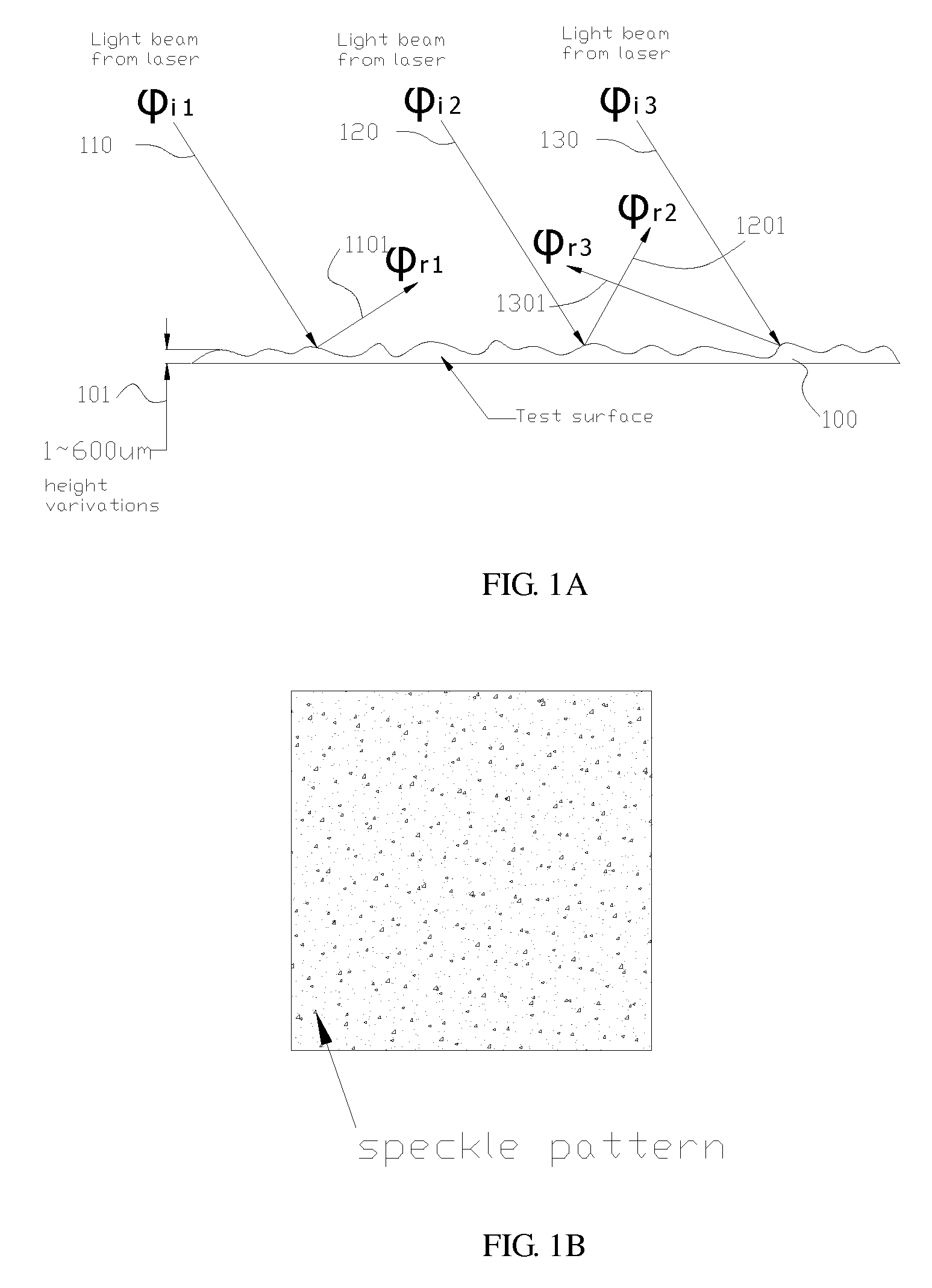
surface pattern variation than the standard LED based optical mice. However, by projecting a laser beam onto a surface with sufficient roughness, i.e. the average height variations of the surface is larger than the wavelength of that laser beam, the surface will exhibits a speckled appearance which is not observed when the surface is illuminated with ordinary light, such as the LED light of a standard LED mouse, as the speckle pattern is a random intensity pattern produced by the mutual interference of coherent laser beam that are subject to phase differences and/or intensity fluctuations. The method and the optical system of the invention controls the speckle sizes and the speckle pattern distribution by adjusting the bandwidth of a coherent laser beam being emitted out of the laser

Problems solved by technology

Furthermore, the real and ima

Method used


Image

  • Method of speckle size and distribution control and the optical system using the same
  • Method of speckle size and distribution control and the optical system using the same
  • Method of speckle size and distribution control and the optical system using the same

Examples


Embodiment Construction

[0058]For your esteemed members of reviewing committee to further understand and recognize the fulfilled functions and structural characteristics of the invention, several preferable embodiments cooperating with detailed description are presented as the follows.

[0059]Please refer to FIG. 14 to FIG. 18 and FIG. 20, which show respectively various optical system and their methods of speckle size and distribution control, As seen in FIG. 20, an optical system is arranged inside a housing 2020 of a laser computer mouse. Preferably, the optical system 2020 is primarily composed of: a laser device 1410 (or 1510, or 1610, or 1710, or 1810), a lens set 1420 (or 1520, or 1620, or 1720, or 1820) and an imaging device 1430 (or 1530, or 1630, or 1730, or 1830), as seen in FIG. 14 (or in FIG. 15, or in FIG. 16, or in FIG. 17, or in FIG. 18), in which the laser device 1410 (or 1510, or 1610, or 1710, or 1810) is used as a light source for providing a laser beam to the optical system 2020; the len...


PUM


Abstract

A method of speckle size and distribution control and the optical system using the same are disclosed. The optical system is arranged inside a housing of a computer mouse that is primarily composed of a laser unit, a lens set, an image sensing unit and a digital signal processing unit. It is known that by projecting a laser beam onto a surface with sufficient roughness, the surface will exhibits a speckled appearance as the speckle pattern is a random intensity pattern produced by the mutual interference of coherent laser beam that are subject to phase differences and/or intensity fluctuations. Thus, the present invention provides an optical system capable of controlling the speckle sizes and the speckle pattern distribution by adjusting the bandwidth of a coherent laser beam being emitted out of the laser light source of the optical system as well as by adjusting the distance between an image plane of the digital signal processing unit and the rough surface being illuminated by the coherent laser beam, so that the distribution of the resulting speckle pattern and the size of each speckle thereof can match with the effective pixel size of different image sensing units used in the optical system. The method and optical system is advantageous in its simple optical path, by which the mechanical structure accuracy is minimized that facilitates and enhances manufacturers of different image sensing units to use speckle patterns for determining how far the optical system has moved and in which direction it is moved.

Description

FIELD OF THE INVENTION[0001]The present invention relates to a method of speckle size and distribution control and the optical system using the same, and more particularly, to an optical system which uses a laser unit and a lens set designed specifically for the laser unit instead of the conventional LED unit and its lens set with light collimation ability as its light source so as to controls the speckle sizes and the speckle pattern distribution by adjusting the bandwidth of a coherent laser beam being emitted out of the laser unit as well as by adjusting the distance between an image plane of the digital signal processing unit and the rough surface being illuminated by the coherent laser beam, by which the distribution of the resulting speckle pattern and the size of each speckle thereof can match with the effective pixel size of different image sensing units used in the optical system. The method and optical system is advantageous in its simple optical path, by which the mechani...

Claims


Application Information

Patent Timeline
IPC IPC(8): G01B11/02
CPCG06F3/0317
Inventor LIN, TIMOTHY
Owner LEAHSIN TECH
Why Eureka
Try Eureka