Devices and methods for production of cell aggregates

a cell aggregate and cell technology, applied in the field of cell aggregate devices and methods, can solve the problems of inability to achieve automation and scale-up, inability to consistently form high-quality aggregates in hesc cultured using standard techniques, and inefficiency and contamination of residuals, etc., to achieve the effect of reducing the chaos and disorder characteristi

Inactive Publication Date: 2011-04-14
UNGRIN MARK +1
View PDF21 Cites 20 Cited by
  • Summary
  • Abstract
  • Description
  • Claims
  • Application Information

AI Technical Summary

Benefits of technology

[0045]The present application also relates to improved methods of reproducibly and efficiently generating cell aggregates from mammalian pluripotent stem cells such as mammalian embryonic stem cell aggregates or embryoid bodies from embryonic stem cells. The present application also relates to a method of employing controlled cell aggregate production to reproducibly and efficiently generate tissue-level organization within cell aggregates of mammalian pluripotent stem cells such as mammalian embryonic stem cell aggregates or embryoid bodies.
[0055]The application further describes a method that addresses the need in the art for efficient production of tissue-level order within cell aggregates from mammalian pluripotent stem cells, such as mammalian embryonic stem cell aggregates or embryoid bodies from mammalian embryonic stem cells. This method comprises the methods set out above and further comprises an additional step of maintaining the recovered cell aggregates from step (3) in suspension for an extended period; wherein the resulting cell aggregates exhibit tissue level organization within the cell aggregates. The method described substantially reduces the chaos and disorder characteristic of existent protocols and results in cell aggregates that exhibit tissue level organization within the cell aggregates, such as mammalian pluripotent stem cell aggregates, for example, embryonic stem cell aggregates or embryoid bodies. This higher order organization and aggregation is obtainable from single cell suspensions. In one embodiment, tissue level organization is visualized via confocal microscopy by assessing expression of marker proteins, such as E-cadherin and Oct4, and by assessing structural organization, such as columnar morphology and actin cytoskeleton.

Problems solved by technology

The results are inefficiency and contamination with residual, potentially tumourigenic stem cells.
Furthermore, current techniques of EB formation are labour intensive, and not amenable to the automation and scale-up required to produce clinically useful quantities of differentiated cells.
In addition, hESC cultured using standard techniques do not consistently form high-quality aggregates (aggregates are often loose, poorly defined and / or cannot be recovered intact) using these methods.
In one case (Khademhosseini—2006), 95% of cells do not settle into the wells, and in both cases, while EB consistency is improved over standard scraping techniques, substantial non-uniformities still exist.
When the neurectodermal differentiation pathway is interfered with via overexpression of the Nodal gene product (Vallier—2004), some tissue-level order can be seen in human EBs, however this approach is deficient in that it both interferes with normal differentiation pathways and requires genetic modification of the stem cells.

Method used


Image

  • Devices and methods for production of cell aggregates
  • Devices and methods for production of cell aggregates
  • Devices and methods for production of cell aggregates

Examples


example 1

Use of Microwells for the Generation of hESC Aggregates

[0173]A silicon master mould was generated via KOH anisotropic etching techniques as described previously, see FIG. 2 left column, and PDMS replica moulding was employed to generate a tiled array of microwells in PDMS as described above (Paragraphs 0025, 0071), see FIG. 2 center and right columns. Sections of the arrays of 800 and 200 micron PDMS microwells were cut manually to size with a razor blade, and transferred into individual wells in a 96-well plate. A single-cell suspension of hESC cultured on Matrigel was then centrifuged onto the surfaces in the presence of 10 82 M of the ROCK inhibitor Y-27632, and incubated overnight. The following day, the resulting aggregates were recovered by manual pipetting (see FIG. 3). As the PDMS microwell arrays were cut to size manually for this prototype experiment, coverage of the well bottom was imperfect, resulting in the formation of some randomly-sized aggregates from cells that did...

example 2

Generation of Uniform hESC Aggregates without Centrifugation

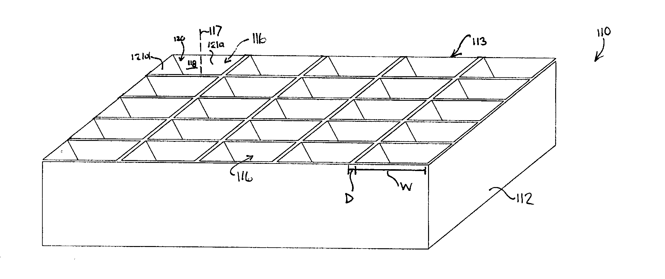
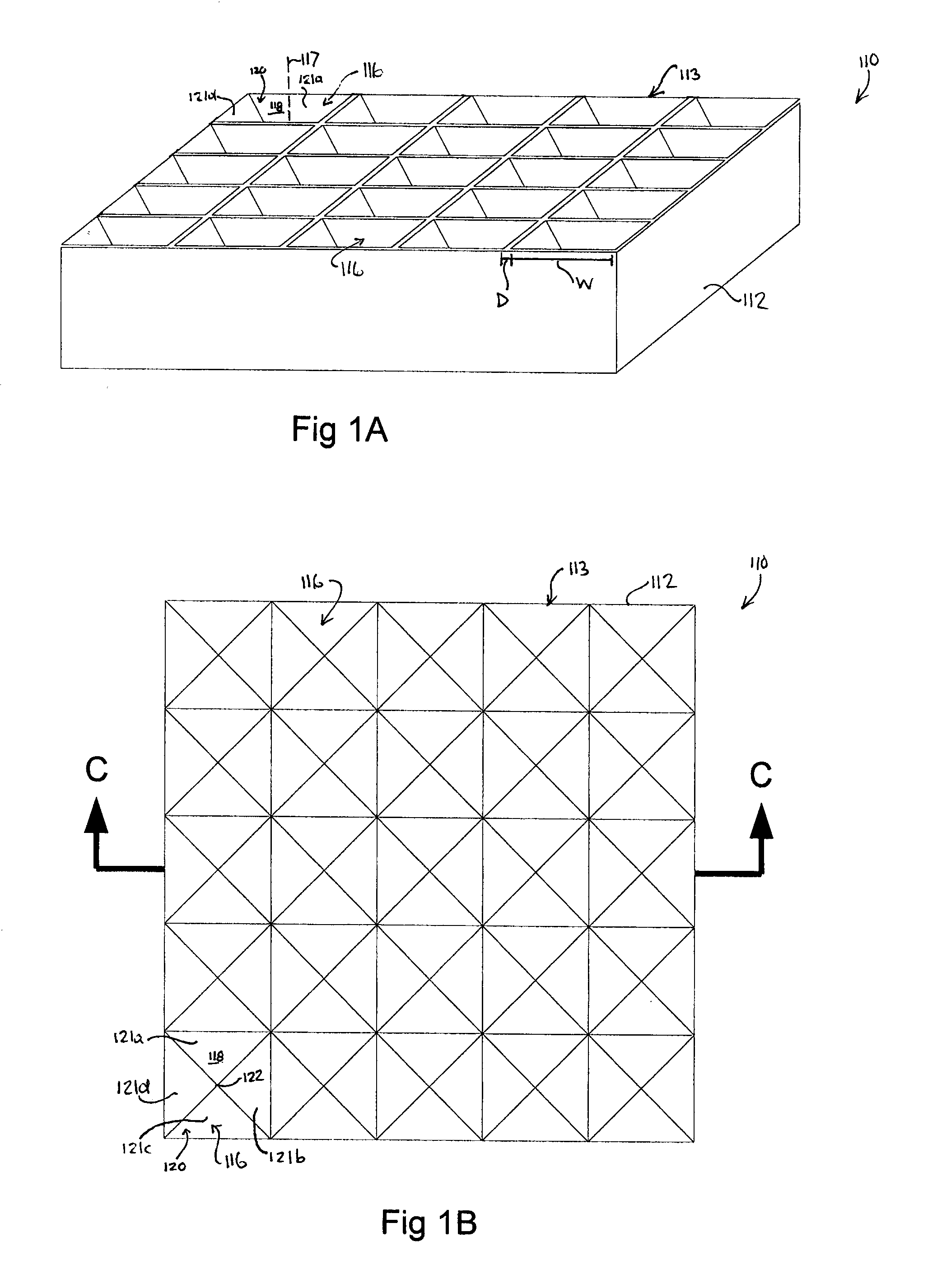
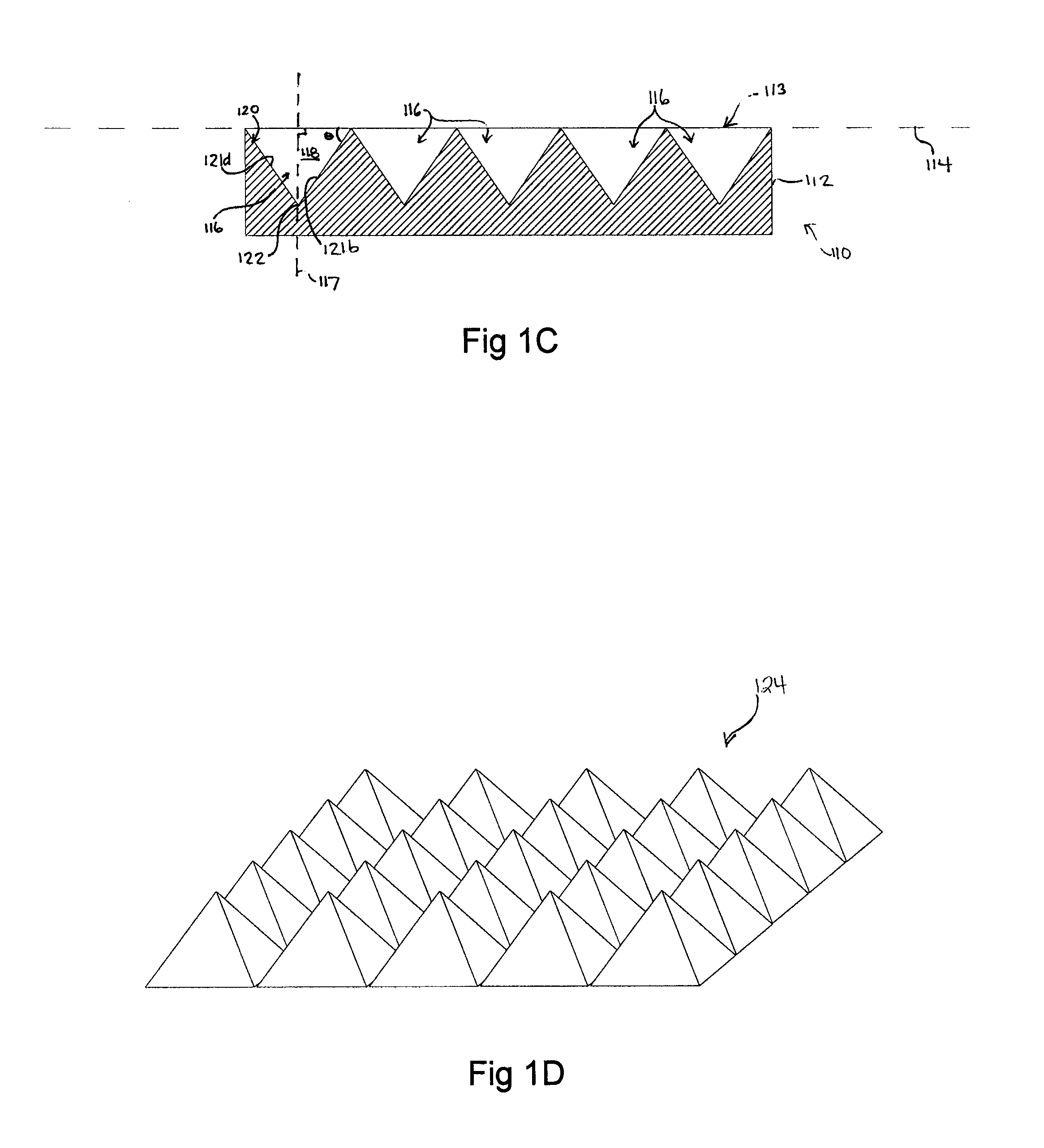
[0174]hESC cultured on Matrigel were treated with 10 μM Y-27632 and allowed to settle into 200 micron PDMS microwells in the device schematized in FIGS. 1A-F and depicted FIG. 2 without further centrifugation, and aggregate for 24 hours. FIG. 4 upper panel shows the aggregates in the microwells, lower panel shows aggregates after extraction.

example 3

Use of Microwells as a Culture Surface

[0175]hESC cultured on MEF were pre-treated with serum containing medium for 48 hours, and centrifuged into 200 micron PDMS microwells. FIG. 5 upper panel shows the aggregates in the microwells after 24 hours. A portion of the aggregates were extracted, the remainder were refed in situ, lower panel shows aggregate development after an additional 48 hours in the wells. As shown in FIG. 6, objects prepared using any technique (in this case forced aggregation of hESC in a 96-well plate format) may be transferred onto microwell surfaces for culturing, facilitating observation and refeeding and inhibiting interactions between objects.


PUM

PropertyMeasurementUnit
angleaaaaaaaaaa
angleaaaaaaaaaa
angleaaaaaaaaaa

Abstract

The present application provides methods and devices for the production and recovery of cell aggregates. In one embodiment, the device is a microwell device with a high density of microwells. The application also provides a device for extracting cell aggregates such as stem cells or embryoid bodies from well plates. Such cell aggregates are used for the differentiation of pluripotent stem cells such as embryonic stem cells, in the fields of developmental biology and regenerative medicine / tissue engineering.

Description

FIELD OF THE INVENTION[0001]The present application relates to devices and methods for the formation of cell aggregates, preferably of pluripotent stem cells such as embryonic stem cells. Such cell aggregates are used for the differentiation of pluripotent stem cells such as embryonic stem cells, in the fields of developmental biology, cellular therapies and regenerative medicine.BACKGROUND OF THE INVENTION[0002]Early embryogenesis is a complex but highly organized process. Specific genetic programs, activated in response to positional and intracellular cues allow the progeny of a single cell to self-organize into tissues, organs, and entire organisms. Human embryonic stem cells (hESC), thought to reflect the pluripotency of the inner cell mass, can be maintained in culture and differentiated into a wide range of cell types. One example of this is the conversion of adherent cultures of hESC to extra-embryonic endoderm via the effects of Bone Morphogenetic Protein-2 (BMP2) (Pera—2004...

Claims


Application Information

Patent Timeline
Patent Type & Authority Applications(United States)
IPC IPC(8): C12N5/071C12M3/00C12N5/09C12Q1/02C12N5/073C12N5/0735
CPCB01L3/5085B01L2200/0668B01L2300/0893B01L2400/0409C12M23/12C12M23/16C12N2502/13C12N5/0606C12N2501/155C12N2501/40C12N2501/48C12N2501/70C12N2533/92C12N5/0603
Inventor UNGRIN, MARKZANDSTRA, PETER
Owner UNGRIN MARK
Why Eureka
Try Eureka