Microfluidic chip

a microfluidic chip and microfluidic fluid technology, applied in the field of microfluidic chips and microfluidic fluid reservoirs, can solve problems such as problems such as ensuring a sufficiently high sterility of fluids, actuating fluids, etc., and achieves a simple and/or robust fluid actuation and high level of sterility

Inactive Publication Date: 2011-04-14
ROBERT BOSCH GMBH
View PDF7 Cites 13 Cited by
  • Summary
  • Abstract
  • Description
  • Claims
  • Application Information

AI Technical Summary

Benefits of technology

[0006]The present invention offers two-component solutions based on separation of microfluidic chip and fluid reservoir and fluid actuation by a distensible surface. Separation of chip and fluid reservoir may in that case have an advantageous effe

Problems solved by technology

In that case, however, actuating the fluid and/or ensuring a

Method used


Image

  • Microfluidic chip
  • Microfluidic chip
  • Microfluidic chip

Examples


Embodiment Construction

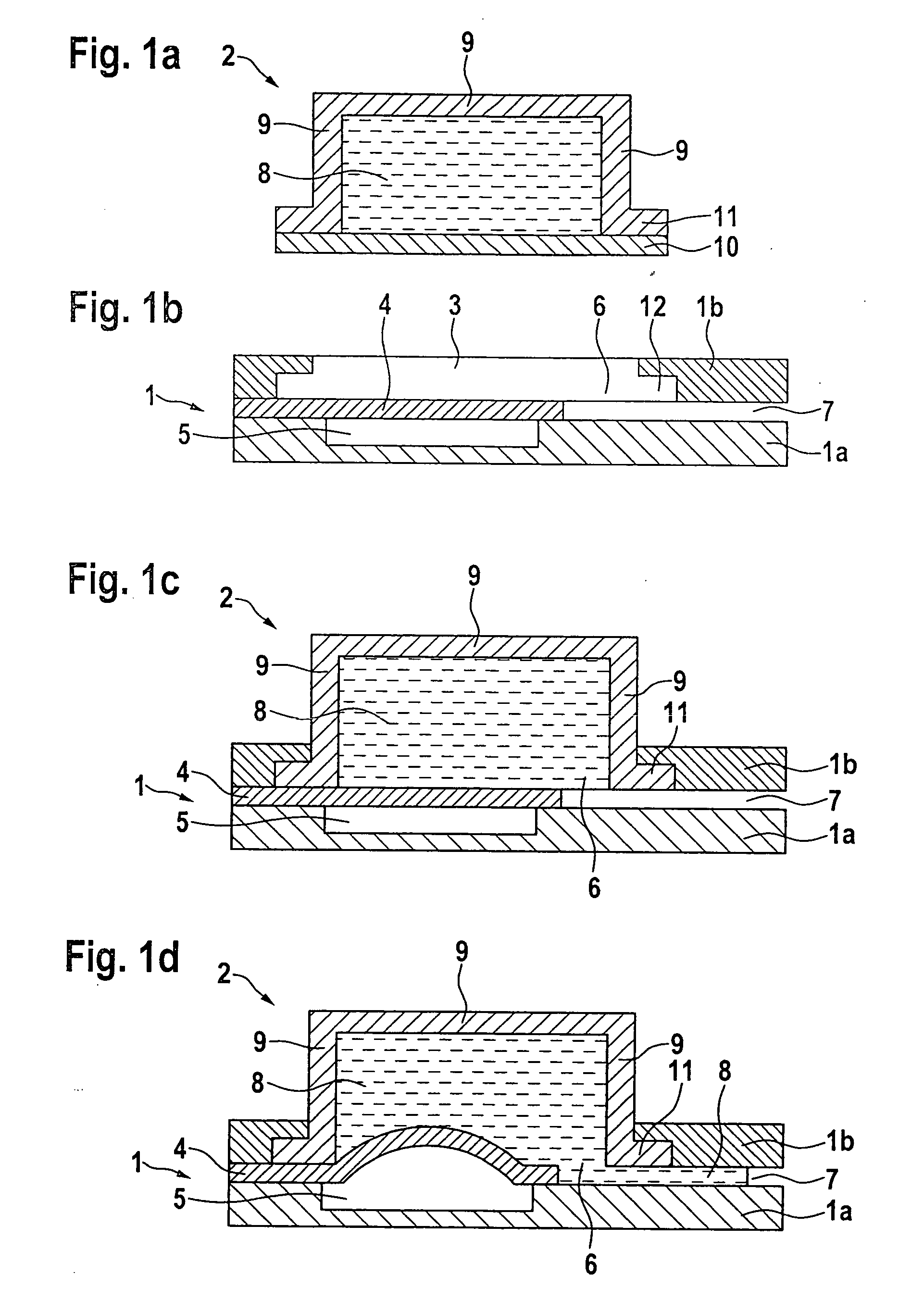
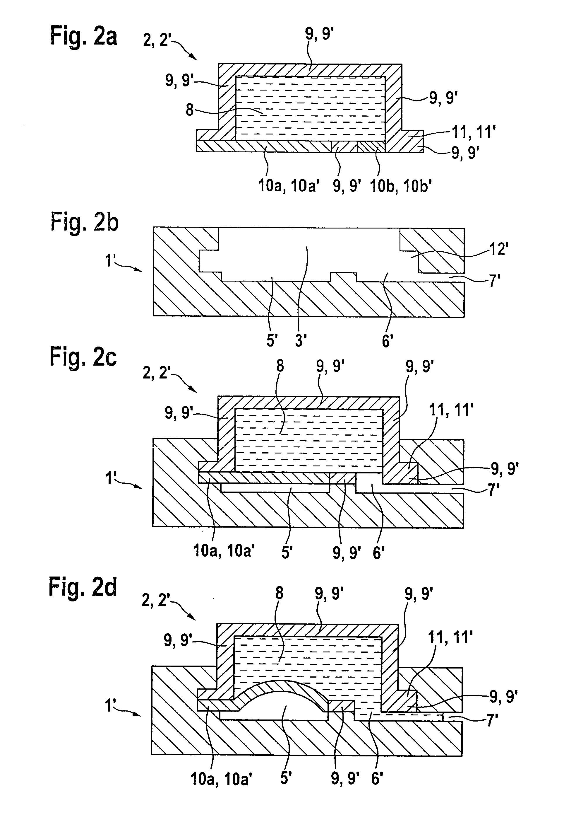
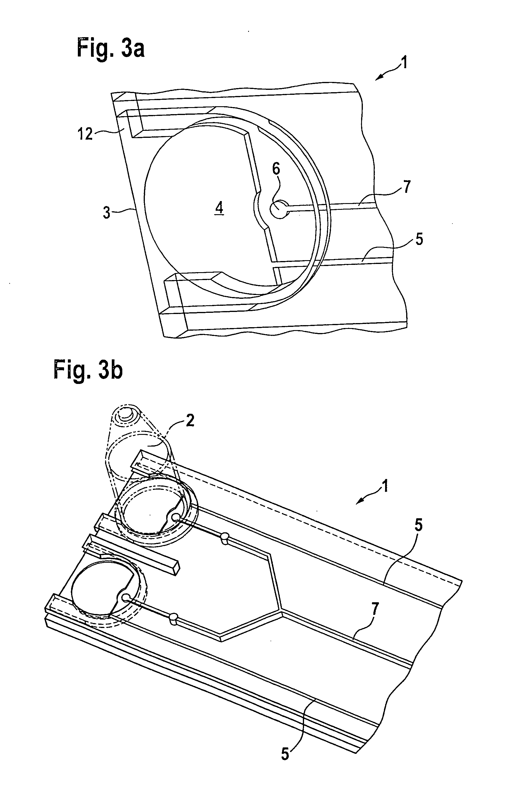
[0032]The present invention further relates to a microfluidic fluid reservoir, for example a microfluidic fluid reservoir partially or completely filled with a fluid, to be received, especially detachably, in a recess of a microfluidic chip described above. In one embodiment, the fluid reservoir has a rigid wall region and an openable wall region, the openable wall region being adapted to contact, when in the mounted state in the recess of the microfluidic chip, the distensible diaphragm and the fluid channel inlet of the microfluidic chip. In another embodiment, the fluid reservoir has a rigid wall region, a distensible, especially an elastic, wall region and an openable wall region, the distensible wall region being adapted to contact, when in the mounted state in the recess of the microfluidic chip, the distensible diaphragm of the microfluidic chip, especially to form a double diaphragm, and the openable wall region being adapted to contact, when in the mounted state in the rece...


PUM


Abstract

A microfluidic chips (1), microfluidic fluid reservoirs (2), microfluidic kits (1,2) comprising a microfluidic chip (1) and a microfluidic fluid reservoir (2), and to methods of operating such microfluidic kits (1,2). According to the invention, at least either the microfluidic chip (1) or the microfluidic fluid reservoir (2) includes a distensible diaphragm (4) or a distensible wall region, respectively, which is distensible into the fluid reservoir (2), with volume displacement taking place, in order to move a fluid (8) out of the fluid reservoir (2) through the fluid channel inlet (6) into a fluid channel (7) of the microfluidic chip (1).

Description

BACKGROUND OF THE INVENTION[0001]1. Field of the Invention[0002]The present invention relates to microfluidic chips, microfluidic fluid reservoirs, microfluidic kits and methods for their operation.[0003]2. Description of Related Art[0004]Lab-on-a-chip (LOC) systems mostly consist of structured parts on which a biological or chemical analysis or production process takes place. In such systems, fluids are in most cases stored in sealed form on the chip itself or supplied to the chip through tubing. In that case, however, actuating the fluid and / or ensuring a sufficiently high sterility of the fluids may be problematic.[0005]Published international patent application WO 99 / 017749 A1 describes a micromechanical valve for fluids.SUMMARY OF THE INVENTION[0006]The present invention offers two-component solutions based on separation of microfluidic chip and fluid reservoir and fluid actuation by a distensible surface. Separation of chip and fluid reservoir may in that case have an advantag...

Claims


Application Information

Patent Timeline
IPC IPC(8): G01N1/10B01L3/00
CPCB01L3/50273B01L3/523B01L2200/027Y10T436/2575B01L2300/0848B01L2300/123B01L2400/0481B01L2200/16
Inventor RUPP, JOCHEN
Owner ROBERT BOSCH GMBH
Why Eureka
Try Eureka