Floor Cleaning Apparatus

a cleaning apparatus and floor technology, applied in the field of cleaning apparatuses, can solve the problems of user inconvenience, cost, and cost, and achieve the effect of enhancing the structural integrity of the connector and uniform thickness

Inactive Publication Date: 2011-04-21
HAYCO MFG
View PDF3 Cites 30 Cited by
  • Summary
  • Abstract
  • Description
  • Claims
  • Application Information

AI Technical Summary

Benefits of technology

[0023]Alternatively, the cylindrical wall may have a generally uniform thickness. The cylindrical wall may however be provided with ribs longitudinally arranged on the exterior surface thereof to enhance structural integrity of the connector. The ribs at or near the second axis may be thinner than the ribs at or near the first axis. With such configuration, the handle portion can similarly pivot forward and backward relative to the base portion more easily than it can pivot sideways.

Problems solved by technology

However, filters, dust containers and air ducting all add cost and complexity to any design, which is particularly sensitive to a low cost product.
Also, replacement of such filters and dust containers by users is an added nuisance and cost.

Method used


Image

  • Floor Cleaning Apparatus
  • Floor Cleaning Apparatus
  • Floor Cleaning Apparatus

Examples


Embodiment Construction

[0030]Embodiments of the present invention are described, by way of examples only, with reference to the following drawings in which:

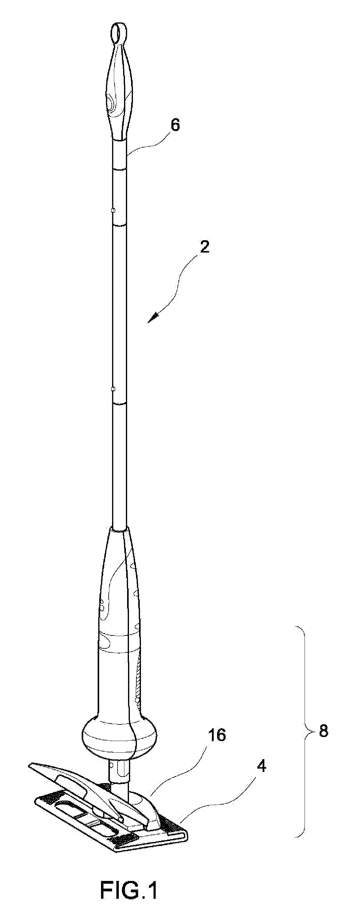
[0031]FIG. 1 is a perspective view showing a floor cleaning apparatus according to an embodiment of the present invention;

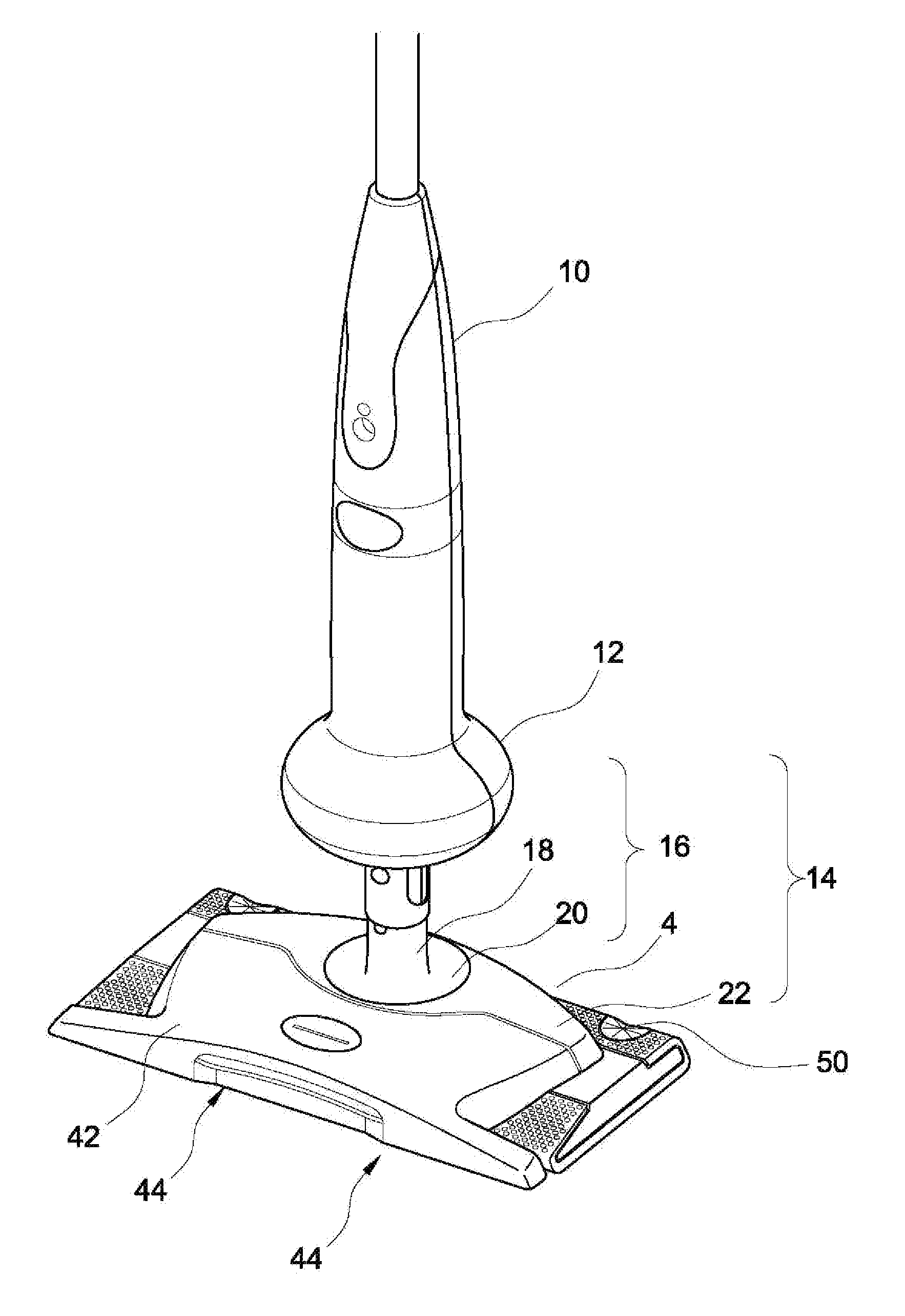
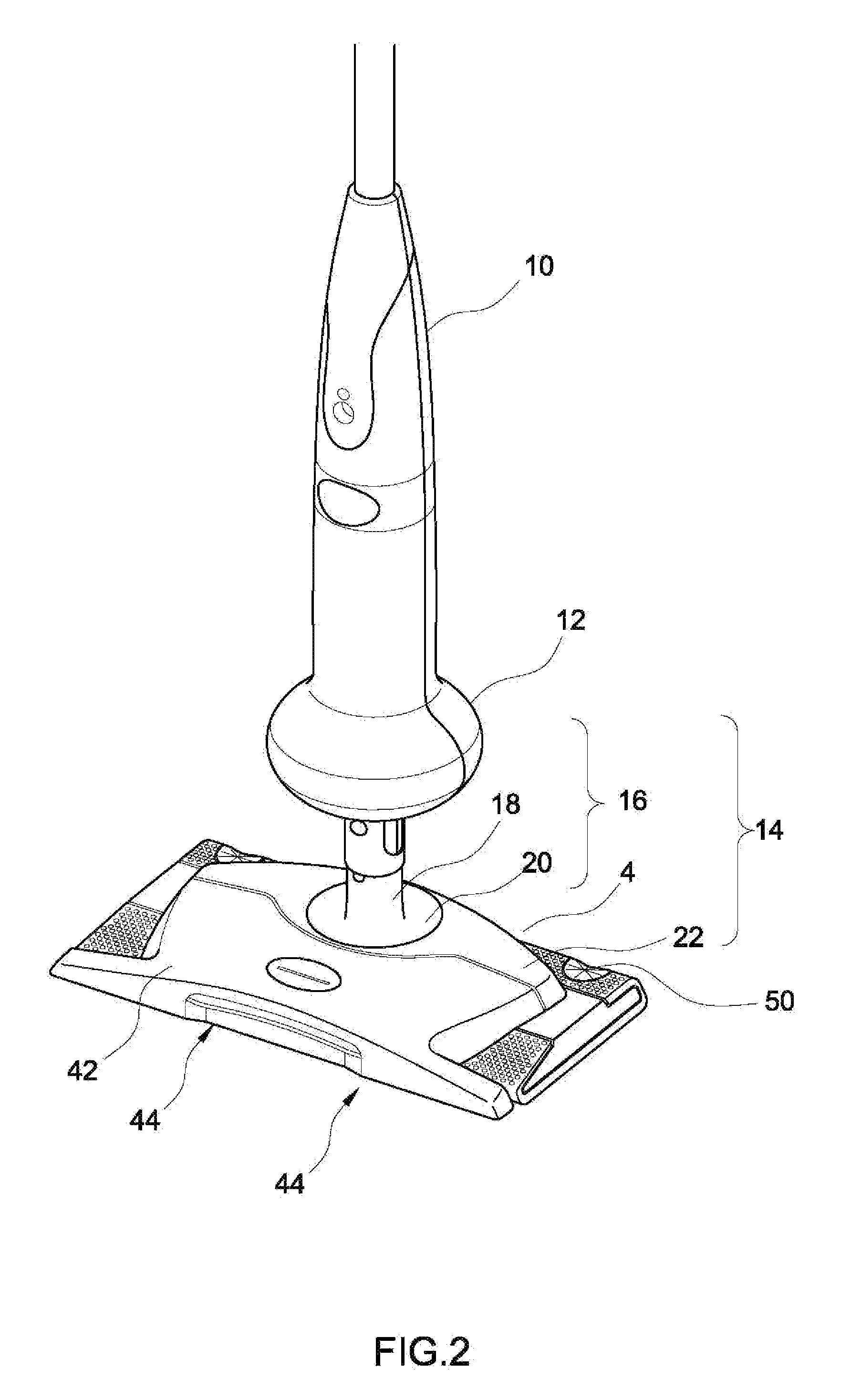
[0032]FIG. 2 is a perspective view showing a lower portion of the floor cleaning apparatus shown in FIG. 1;

[0033]FIG. 3 is a side view showing the lower portion floor cleaning apparatus shown in FIG. 1;

[0034]FIG. 4 is a schematic view of the interior of the lower portion of the floor cleaning apparatus shown in FIG. 1;

[0035]FIG. 5 is another schematic view showing the interior of the lower portion of the floor cleaning apparatus shown in FIG. 1;

[0036]FIG. 6 is a schematic view showing air flow within a part of the lower portion of the cleaning apparatus shown in FIG. 2;

[0037]FIG. 7 is a schematic view showing the configuration of a cleaning sheet fitted to the part of the lower portion shown in FIG. 6;

[0038]FIG. 8 is a schematic vie...


PUM


Abstract

There is provided a floor cleaning apparatus assembly comprising a base portion for engaging a floor during cleaning, means for creating suction whereby air is drawn from the surrounding of the base portion through the base portion via an opening provided at a front end of the base portion, a cleaning sheet provided with a first area for collecting finer dirt particles and a second area for collecting larger dirt particles, means for securing the cleaning sheet to the base portion but exposing the first area of the cleaning sheet, and a channel provided within the floor cleaning apparatus through which suctioned air travels, the channel beginning with the opening at the front end of the base portion, followed by passing through the second area of the cleaning sheet whereby larger dirt particles carried in the air are trapped thereat, and ending at an exit.

Description

FIELD OF THE PRESENT INVENTION[0001]The present invention is related to a cleaning apparatus for floor cleaning.BACKGROUND OF THE PRESENT INVENTION[0002]There is a great variety of implements for floor care on the market. Common variants include upright- and cylinder-type suction cleaners, stick-vacuum cleaners, hand-held vacuums and mops. There are also floor care products that combine vacuum cleaning and mopping. Lightweight stick vacuum cleaners are often equipped with a mopping pad, onto which a cleaning sheet or similar is attached, so that both larger and smaller dust particles can be cleaned off the floor. Many conventional suction cleaners are designed to necessarily equip with a relatively large container for collecting dust and a filter to clean suctioned air before it enters the suction motor. However, filters, dust containers and air ducting all add cost and complexity to any design, which is particularly sensitive to a low cost product. Also, replacement of such filters...

Claims


Application Information

Patent Timeline
Patent Type & Authority Applications(United States)
IPC IPC(8): A47L9/06
CPCA47L9/0686
Inventor IVARSSON, BENGT IVAR ANDERS
Owner HAYCO MFG
Why Eureka
Try Eureka