Harmonic drive using profile shifted gear

a gear shift and harmonic drive technology, applied in the direction of gearing, gearing elements, hoisting equipment, etc., can solve the problems of large harmonic drive size, limitation in reducing the length of the cup, and difficulty in designing and manufacturing thereof, so as to minimize the thickness of flexible gears, improve power transmission efficiency, and minimize the effect of energy loss generated by flexible gear deformation

Inactive Publication Date: 2011-04-21
KOREA INST OF SCI & TECH
View PDF21 Cites 69 Cited by
  • Summary
  • Abstract
  • Description
  • Claims
  • Application Information

AI Technical Summary

Benefits of technology

[0021]According to a double harmonic drive of the invention, since a thickness of a flexible gear can be minimized by using profile shifted gears, energy loss generated when the flexible gear is deformed is minimized so that power transmitting efficiency can be improved.
[0022]Further, a harmonic drive according to the invention can improve the engagement of teeth between a band type of a flexible gear and external gears to have an improved power transmitting characteristic so that a high torque can be transmitted. Further, since two harmonic motions are overlapped with each other into a double harmonic motion, a variety of velocity reduction rate can be obtained, and backlash can be removed.
[0023]Furthermore, a harmonic drive according to the invention enables to manufacture a flexible gear, external gears and connecting sprockets by means of a molding method, whereby manufacturing costs can be reduced in mass production.

Problems solved by technology

That is to say, a single component needs to have different physical properties, which causes designing and manufacture thereof difficult.
For example, there is a limitation in reducing the length of the cup, and, as a result, the size of the harmonic drive becomes large.
Such relative radial motion results in a backlash problem.
Among harmonic drives having a band type of flexible gear applied therein there is a harmonic drive utilizing a double harmonic motion, which is however in need of a set of gear teeth having a plurality of different pitch diameters in the flexible gear, thereby causing lots of manufacturing problems.

Method used


Image

  • Harmonic drive using profile shifted gear
  • Harmonic drive using profile shifted gear
  • Harmonic drive using profile shifted gear

Examples


first embodiment

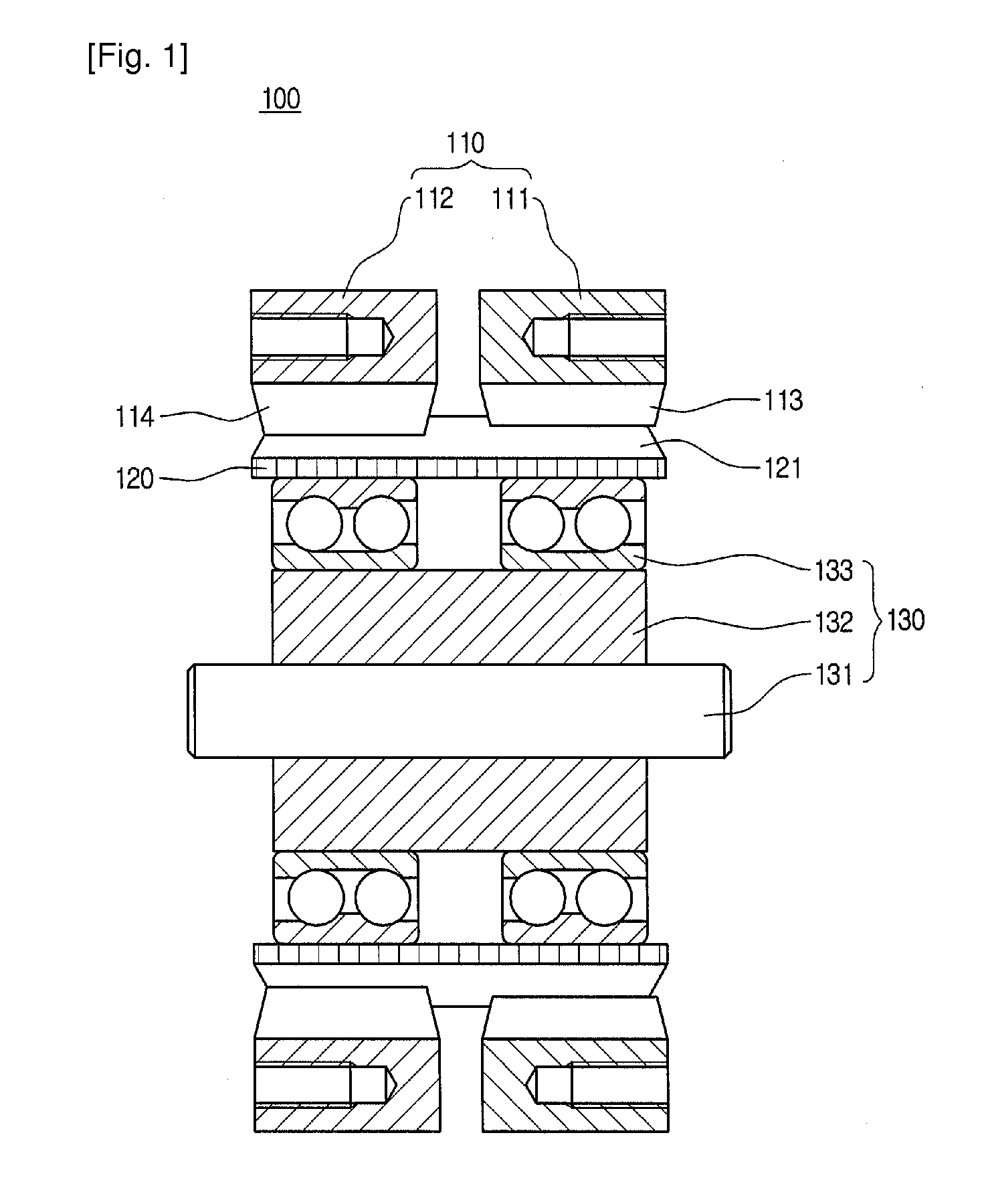
[0037]Referring to FIG. 1, a harmonic drive 100 according to the invention comprises a plurality of a cylindrically-shaped internal gear 110, a flexible gear 120 and a wave generating part 130.

[0038]The internal gear 110 comprises a first internal gear 111 and a second internal gear 112, on inner circumferential surfaces of which first internal teeth 113 and second internal teeth 114 are formed, respectively. Here, the first internal teeth 113 are formed of profile shifted teeth, and the second internal teeth 114 are formed of standard teeth. Therefore, if the first internal gear 111 and the second internal gear 112 are formed of the same module, they have the same pitch diameters but different number of teeth. Assuming that the first internal gear 111 and the second internal gear 112 formed of standard teeth profiles have 100 teeth and 102 teeth respectively, in order that the first internal gear 111 and the second internal gear 112 are formed of the same module, the first internal...

second embodiment

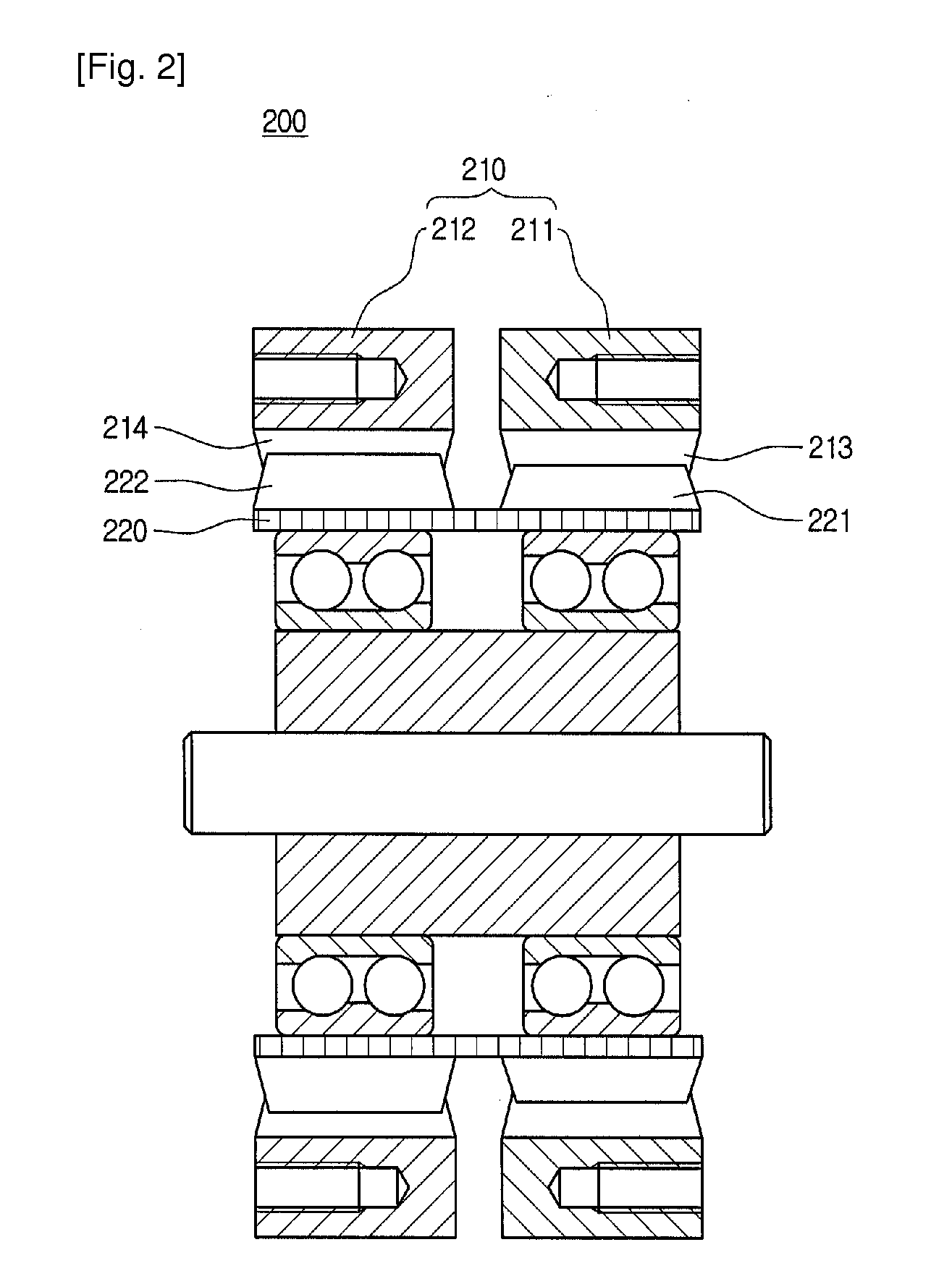
[0050]Referring to FIG. 2, in a harmonic drive 200 according to the invention, in order to provide different number of teeth, first and second internal gears 211, 212 are formed of standard gears, and a flexible gear 220 is formed of profile shifted gears. That is to say, first and second internal teeth 213, 214 of the first and second internal gears 211, 212 are formed of the same number of standard teeth, whereas, in case of the flexible gear 220, first external teeth 221 which engage with the first internal teeth 213 are formed of profile shifted teeth, and second external teeth 222 which engage with the second internal teeth 214 is formed of standard teeth.

[0051]In other words, the harmonic drive 200 according to the second embodiment of the invention is configured such that the internal gears have the same number of teeth and the flexible gear has a difference in the number of teeth between the first external teeth and the second external teeth instead of having a difference in...

third embodiment

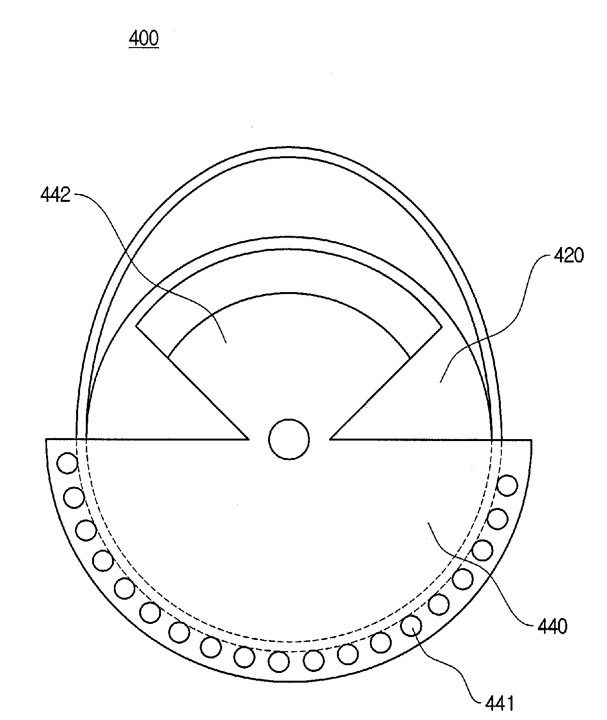
[0055]FIG. 3 is a perspective view of a harmonic drive according to the invention, and FIG. 4 is a cross-sectional view of the harmonic drive shown in FIG. 3.

[0056]Referring to FIGS. 3 and 4, a harmonic drive according to the third embodiment of the invention comprises a first external gear 321 and a second external gear 331 which are disposed parallel coaxially. From both sides of the center of the first external gear 321, a rotating shaft 323 is extended outwardly, and a second external gear 331 is disposed on a side of the rotating shaft 323.

[0057]Further, on an outer side of the first and second external gears 321, 331 a circular band type of flexible gear 310 is arranged. The flexible gear 310 is provided, on its inner circumferential surface, with first and second internal teeth 311, 312 which engage with first and second external teeth 322, 332 of the first and second gear 321, 331, respectively. Furthermore, a pitch circumference length of the flexible gear 310 is longer tha...


PUM


Abstract

A harmonic drive according to the present invention comprises a plurality of internal gears; a band type of flexible gear provided with teeth engaged with each of the internal gears on its outer circumferential surface, the flexible gear having a pitch circumference length shorter than that of said internal gears; and a wave generating part disposed on an inner side of said flexible gear, the wave generating part generating a plurality of harmonic motions by deforming said flexible gear as the wave generating part rotates. Further, said flexible gear is formed integrally to engage with said plurality of internal gears so that the plurality of harmonic motions are overlapped, and one or more of said plurality of internal gears and said flexible gear are formed of profile shifted gears.

Description

TECHNICAL FIELD[0001]The present invention relates to a harmonic drive, more particularly to a harmonic drive which decelerates an actuator by using a flexible gear.BACKGROUND ART[0002]The harmonic drive generally comprises a cylindrically-shaped internal gear, a cup-shaped flexible gear and a wave generator. The wave generator is generally in the form of an ellipse and is disposed on an inner side of said flexible gear. The flexile gear provided with said wave generator is disposed on an inner circumferential surface of said internal gear. An inner circumferential surface of the internal gear and an outer circumferential surface of the flexible gear are generally configured so that the surfaces each has a tooth profile machined to have no slippage between them.[0003]In the harmonic drive, when the internal gear is fixed and the wave generator is rotated, due to a difference of circumference lengths of the flexible gear and the internal gear, a slight rotation occurs in the flexible...

Claims


Application Information

Patent Timeline
Patent Type & Authority Applications(United States)
IPC IPC(8): F16H55/14F16H1/32
CPCF16H49/001Y10T74/18544Y10T74/19633Y10T74/19F16H1/32
Inventor CHO, CHANG-HYUNKIM, MUNSANG
Owner KOREA INST OF SCI & TECH
Why Eureka
Try Eureka