Egg Cooker Device

a technology of egg cooker and egg shell, which is applied in the field of egg cooker devices, can solve the problems of not being able to provide mechanical drive, not being able to generally measure accurately, and being likely to require regular maintenance, so as to achieve the effect of not impairing the water sealing effect of the container wall

Inactive Publication Date: 2011-04-21
BONSELL STUART
View PDF7 Cites 18 Cited by
  • Summary
  • Abstract
  • Description
  • Claims
  • Application Information

AI Technical Summary

Benefits of technology

[0004]The present invention provides a drive means for the egg to be raised to the top of the container. The drive means in operation is able to raise the cooked egg to the container top and this is done without impairing the water sealing effectiveness of the container wall.
[0008]The drive means inside the container may be a drive disc supporting one or more permanent magnets. Preferably, the drive disc supports two bar magnets which are curved in shape so as to be able to lie along the circumference of a circle. The drive disc may be arranged to completely enclose the relevant permanent magnets. The drive disc may be located coaxially with a drive screw so that a rotational movement of the disc will cause the screw to be rotated. A platform for supporting an egg may be mounted on a nut which is coupled to the drive screw such that rotation of the screw will cause the platform to be raised or lowered. The platform may be provided with radially aligned slots which are able to slide along vertical ribs in the walls of the container. The ribs thus serve to prevent any rotation of the egg platform and the nut when the drive screw is turned.

Problems solved by technology

This arrangement is capable of doing a satisfactory job but it is not generally able to measure a precise time interval and accurate timing would be preferred by many consumers who require carefully soft boiled eggs.
The drive means which is required to move the egg to the open top of the container is required to operate below the surface level of the heated water in the container and it is not easy to provide a mechanical drive means which will work reliably under these conditions.
It would be possible to provide a waterproof seal to enable a motor shaft to pass through a wall of the container but any such seal is likely to require regular maintenance and this would eventually cause a problem in a small domestic appliance which might be expected to be used every day over a lifetime of several years.

Method used


Image

  • Egg Cooker Device
  • Egg Cooker Device
  • Egg Cooker Device

Examples


Embodiment Construction

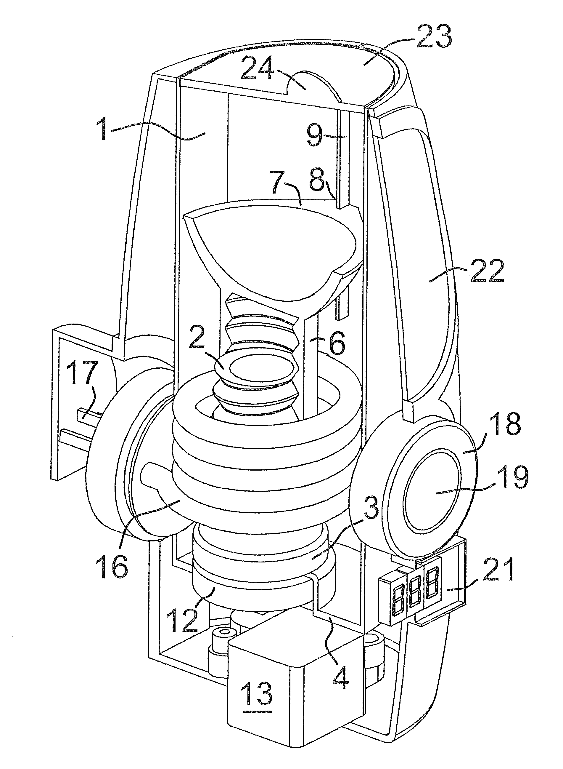
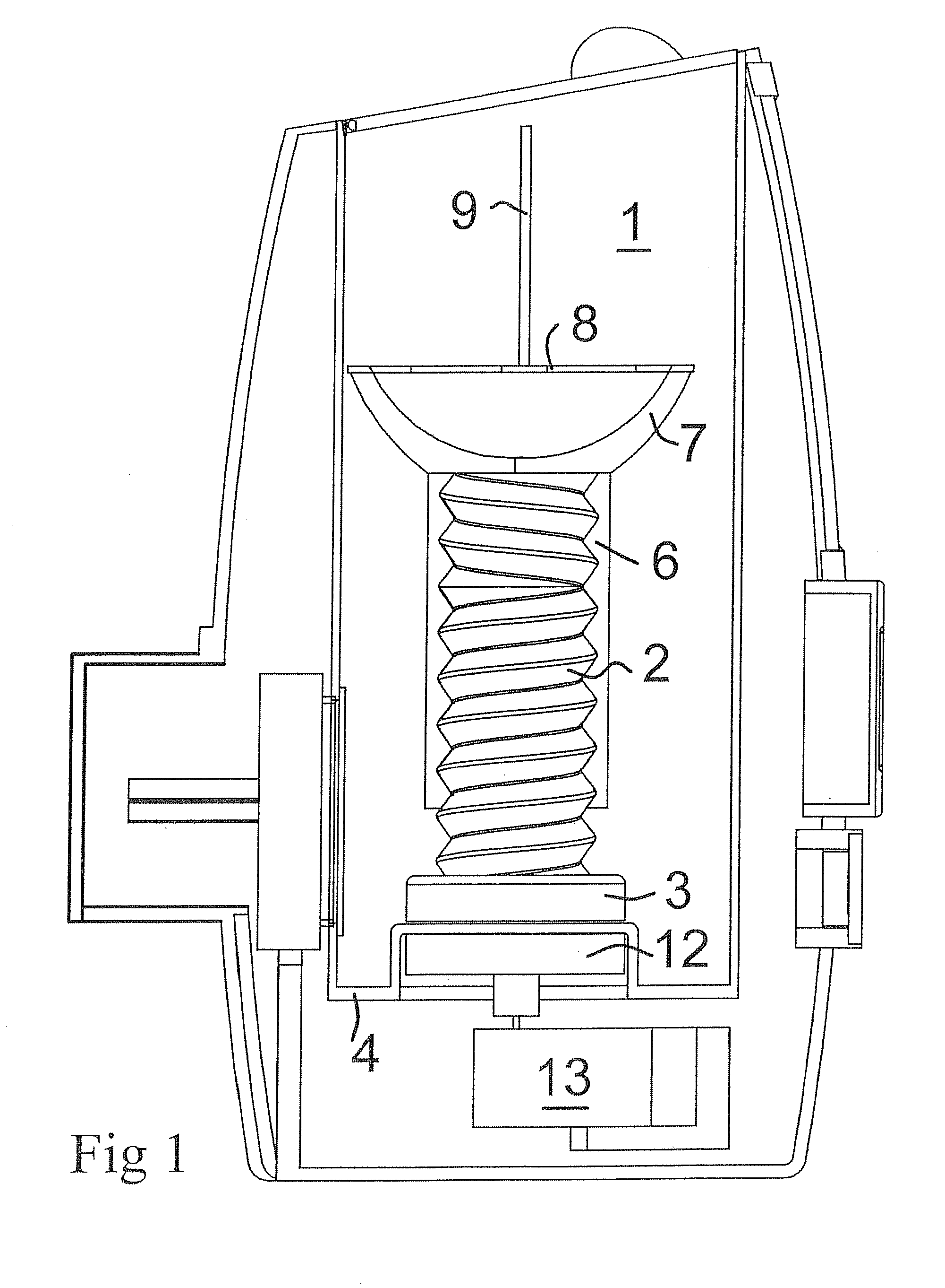
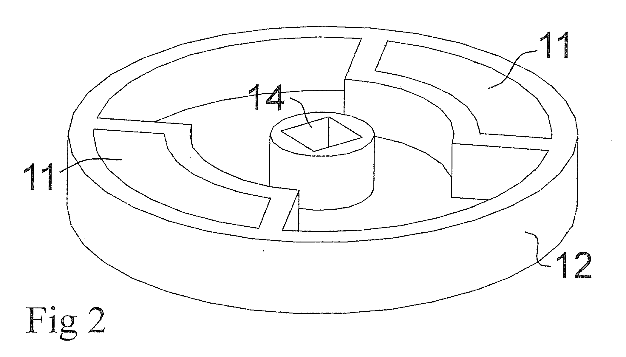
[0020]As depicted in FIG. 1, the egg cooker device includes a water container 1 of a generally cylindrical shape which encloses an electric heating element (not shown) and a drive means formed by a drive screw 2 which is provided at a lower end with a drive disc 3. The drive disc 3 lies in contact with a base wall 4 of the container. The drive screw 2 is coupled to a cylindrical nut 6 which carries an egg support platform 7 at its upper end. A rotation of the drive screw 2 with respect to the nut 6 will thus cause the nut 6 to be moved along the longitudinal axis of the screw 2. A suitable rotation of the drive screw 2 will serve to move the egg support platform 7 up to the top of the container 1 or alternatively will allow the platform 7 to be lowered until the length of the nut 6 supporting the platform 7 is completely accommodated on the screw 2.

[0021]The egg support platform 7 is provided with slots 8 which are arranged to slide along vertical ribs 9 located on an inner wall of ...


PUM


Abstract

An egg cooker device comprises a water container 1 and an electric heating element, the container including a support platform 7 capable of lowering an egg into a body of water in the container 1, an electric motor 13 arranged for moving the platform 7 from a rest position at an open top of the container to an egg heating position within the container, a timer device connected to the motor such that the platform will remain in the egg heating position for a predetermined time interval, in which the support platform 7 includes a drive means 3 linked by a magnetic coupling to a drive source 12 located outside the container 1. This construction uses a magnetic coupling to get a drive from the motor 13 shaft through the wall of the container, it thus avoids a need to provide a water sealed opening for the shaft in the container 1 wall.

Description

BACKGROUND OF THE INVENTION[0001]This invention relates to an egg cooker device. There have been many different constructions proposed for carrying out this relatively simple household task. One particular device provides a wire basket by which the egg is supported in a bath of boiling water and a mechanical lift arrangement is then actuated after a required time interval to raise the egg out of the water. This arrangement is capable of doing a satisfactory job but it is not generally able to measure a precise time interval and accurate timing would be preferred by many consumers who require carefully soft boiled eggs.[0002]An egg cooker with an accurately adjustable timer is shown in patent specification No. GB2423007. The specification discloses an automatic egg boiler comprising a water container, an electric heating element, a drive means able to move an egg to an open top of the container when actuated and an electronic timer. This egg boiler is thus able to work on its own wit...

Claims


Application Information

Patent Timeline
Patent Type & Authority Applications(United States)
IPC IPC(8): A47J29/04
CPCA47J29/04
Inventor BONSELL, STUART
Owner BONSELL STUART
Why Eureka
Try Eureka