Cutting elements configured to generate shear lips during use in cutting, earth boring tools including such cutting elements, and methods of forming and using such cutting elements and earth boring tools

a technology of cutting elements and cutting elements, which is applied in the field of cutting elements configured to generate shear lips during use in cutting, earth boring tools including such cutting elements, and methods of forming and using such cutting elements and earth boring tools. it can solve the problems of increasing the penetration rate (rop), catastrophic failure of cutting elements, and increasing the total area of wear scars

Active Publication Date: 2011-04-21
ELEMENT SIX LTD +1
View PDF22 Cites 59 Cited by
  • Summary
  • Abstract
  • Description
  • Claims
  • Application Information

AI Technical Summary

Benefits of technology

[0014]In some embodiments, a first layer of polycrystalline diamond material is formed over a surface of a substrate, and the first layer of polycrystalline diamond material is formulated to exhibit a first wear resistance. A second layer of polycrystalline diamond material is foamed on a side of the first layer of polycrystalline diamond material opposite the cutting element substrate, and the second layer of polycrystalline diamond material is formulated to exhibit a second wear resistance higher than the first wear resistance.
[0015]In additional embodiments, a first layer of polycrystalline diamond material is formed over a surface of the cutting element substrate, and the first layer of polycryst

Problems solved by technology

The portion of the diamond table at the wear scar projecting outward beyond the adjacent rubbing surface of the cemented carbide substrate has been referred to as a “shear lip.” The formation of such a shear lip was thought to beneficially result in an increased rate of penetration (ROP), although the shear lip was also frequently believed to be the source of delamination or spalling of the diamond table, which often leads to catastrophic failure of the cutting element.
Furthermore, as a PDC cutting element wears duri

Method used


Image

  • Cutting elements configured to generate shear lips during use in cutting, earth boring tools including such cutting elements, and methods of forming and using such cutting elements and earth boring tools
  • Cutting elements configured to generate shear lips during use in cutting, earth boring tools including such cutting elements, and methods of forming and using such cutting elements and earth boring tools
  • Cutting elements configured to generate shear lips during use in cutting, earth boring tools including such cutting elements, and methods of forming and using such cutting elements and earth boring tools

Examples


Embodiment Construction

[0027]Some of the illustrations presented herein are not meant to be actual views of any particular cutting element or earth-boring tool, but are merely idealized representations which are employed to describe the present invention. Additionally, elements common between figures may retain the same numerical designation.

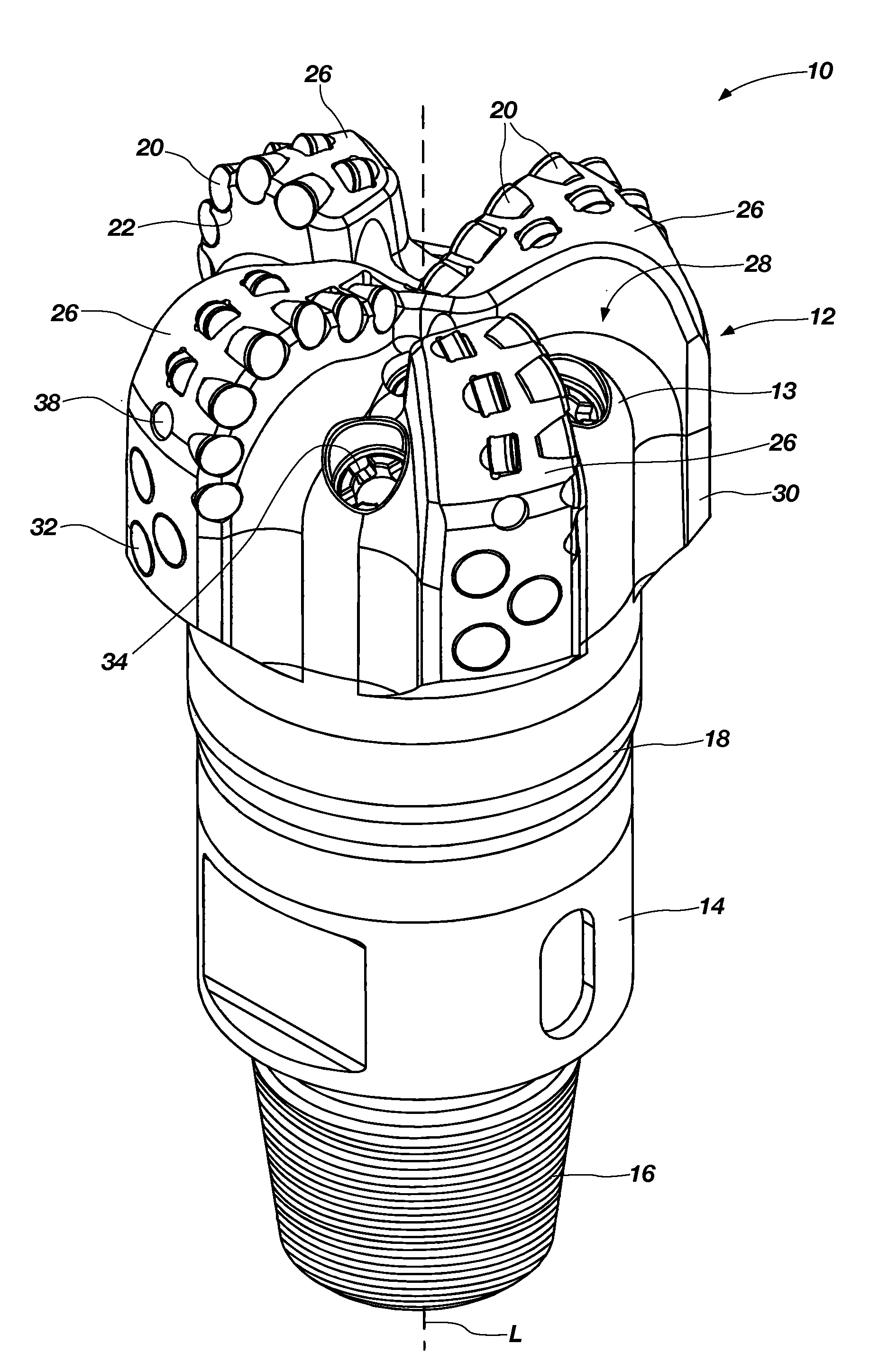
[0028]As used herein, the term “front surface” of a cutting element means and includes the generally planar end surface of a cutting element at what would be the leading end of the cutting element when the cutting element is mounted to a drilling tool and rotated about a rotational axis of the tool within a wellbore (the “rotationally leading” end of the cutting element). The front surface of a cutting element may comprise a major, exposed surface of a diamond table on the cutting element and may also be referred to as the “cutting face” of the cutting element.

[0029]As used herein, the term “lateral surface” of a cutting element means and includes the one or more late...


PUM

PropertyMeasurementUnit
Grain sizeaaaaaaaaaa
Lengthaaaaaaaaaa

Abstract

Cutting elements for earth-boring tools may generate a shear lip at a wear scar thereon during cutting. A diamond table may exhibit a relatively high wear resistance, and an edge of the diamond table may be chamfered, the combination of which may result in the formation of a shear lip. Cutting elements may comprise multi-layer diamond tables that result in the formation of a shear lip during cutting. Earth-boring tools include such cutting elements. Methods of forming cutting elements may include selectively designing and configuring the cutting elements to form a shear lip. Methods of cutting a formation using an earth-boring tool include cutting the formation with a cutting element on the tool, and generating a shear lip at a wear scar on the cutting element. The cutting element may be configured such that the shear lip comprises diamond material of the cutting element.

Description

CROSS-REFERENCE TO RELATED APPLICATIONS[0001]This application claims the benefit of U.S. Provisional Patent Application Ser. No. 61 / 248,279, filed Oct. 2, 2009, the disclosure of which is hereby incorporated herein in its entirety by this reference. This application also claims the benefit of U.S. Provisional Patent Application Ser. No. 61 / 248,183, filed Oct. 2, 2009, the disclosure of which is hereby incorporated herein in its entirety by this reference.TECHNICAL FIELD[0002]Embodiments of the present invention generally relate to cutting elements that include a table of superabrasive material (e.g., diamond or cubic boron nitride) formed on a substrate, to earth-boring tools including such cutting elements, and to methods of forming such cutting elements and earth-boring tools.BACKGROUND[0003]Earth-boring tools for forming wellbores in subterranean earth formations may include a plurality of cutting elements secured to a body. For example, fixed-cutter earth-boring rotary drill bit...

Claims


Application Information

Patent Timeline
IPC IPC(8): E21B7/00E21B10/46B24D18/00
CPCB24D18/0009E21B10/5735B24D3/10E21B10/567C23C30/005E21B10/43B22F2998/00C22C26/00
Inventor SCOTT, DANNY E.SKEEM, MARCUS R.LUND, JEFFREY B.LIVERSAGE, JOHN H.ADIA, MOOSA MAHOMED
Owner ELEMENT SIX LTD
Why Eureka
Try Eureka