Sample storage apparatus

a technology for storage apparatus and samples, applied in the direction of display hangers, dismountable cabinets, cabinets, etc., can solve the problems of increasing manufacturing costs, and achieve the effect of effective and maximally ensuring the space for storing samples

Inactive Publication Date: 2011-04-21
KOREA INST OF GEOSCI & MINERAL RESOURCES
View PDF11 Cites 15 Cited by
  • Summary
  • Abstract
  • Description
  • Claims
  • Application Information

AI Technical Summary

Benefits of technology

[0008]Accordingly, the present invention has been made to solve the above-mentioned problems occurring in the prior art, and an object of the present invention is to provide a sample storage apparatus in that a multil...

Problems solved by technology

However, in the conventional sample storage apparatus, there is a problem in that the entire size of the sample storage ...

Method used


Image

  • Sample storage apparatus
  • Sample storage apparatus
  • Sample storage apparatus

Examples


Embodiment Construction

[0033]Hereinafter, the present invention will be described with reference to accompanying drawings.

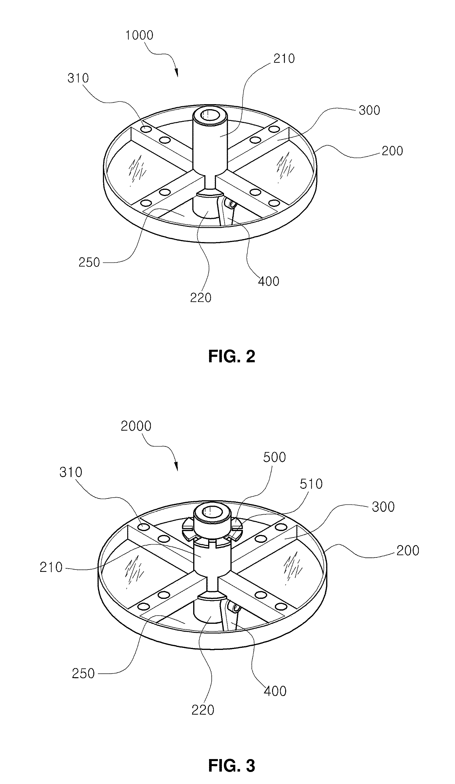
[0034]FIG. 2 is a perspective view illustrating an upper rotary unit of a sample storage apparatus according to the present invention.

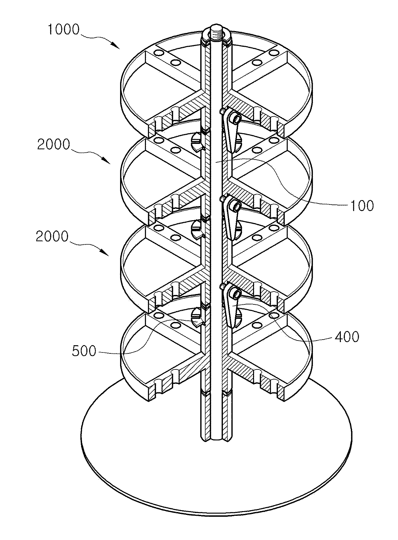
[0035]As shown in FIG. 2, the upper rotary unit 1000 of the sample storage apparatus according to the present invention basically includes a first rotary table 200 having a first upper cylinder portion 210 protruded upward from an upper middle portion thereof and allowing a rotating axis 100 to be inserted therein and a first lower cylinder portion 220 protruded downward from a lower middle portion thereof and allowing the rotating axis 100 to be inserted therein; at least one first partition members 300 for partitioning off an upper surface of the first rotary table 200 formed at the upper surface of the first rotary table 200; and a first fixing member 400 coupled to one side of an outer circumference of the first lower cylinder portion 220 through a f...


PUM


Abstract

Disclosed is a sample storage apparatus in that a multilayered rotary table is formed in a liquid nitrogen vessel, so that a plurality of sample storage boxes is stored in the multilayered rotary table, whereby it can effectively and maximally ensure the space for storing the samples. The sample storage apparatus includes: a rotating axis 100; a rotary table 200 having an upper cylinder portion 210 protruded upward from an upper middle portion thereof and allowing the rotating axis 100 to be inserted therein and a lower cylinder portion 220 protruded downward from a lower middle portion thereof and allowing the rotating axis 100 to be inserted therein; at least one partition member 300 for partitioning off an upper surface of the rotary table 200 formed at the upper surface of the rotary table 200; a fixing member 400 coupled to one side of an outer circumference of the lower cylinder portion 220 through a hinge coupling portion 410 and having a lower portion protruded downward from a lower end of the lower cylinder portion 220 and a slanting portion formed at one side of an upper end thereof so as to form a fixing gap angle 430; and a latching member 500 formed along an outer circumference of the upper cylinder portion 210 and having a plurality of insertion holes 510 for allowing a lower end of the fixing member 400 to be inserted therein.

Description

REFERENCE TO RELATED APPLICATIONS[0001]This application claims the priority benefit of Korean Patent Application No. 10-2009-0098950 filed on Oct. 16, 2009, the entire contents of which are incorporated herein by reference.FIELD OF THE INVENTION[0002]The present invention relates to a sample storage apparatus. More particularly, the present invention relates to a sample storage apparatus in that a multilayered rotary table is formed in a liquid nitrogen vessel, so that a plurality of sample storage boxes is stored in the multilayered rotary table, whereby it can effectively and maximally ensure the space for storing the samples.BACKGROUND OF THE INVENTION[0003]Generally, a sample storage apparatus serves to store a liquid oxygen, a liquid nitrogen, an argon, or a carbon dioxide gas and so on.[0004]Especially, the sample storage apparatus serves to store a cord blood, a gene, a cell, a bone marrow, a fertilized egg, a white blood corpuscle, valves of the heart, various microorganisms...

Claims


Application Information

Patent Timeline
IPC IPC(8): A47F5/02
CPCA01N1/0242C12M23/08C12M23/44
Inventor JIN, JAE HWAKIM, JUN HOKIM, MIN JUN
Owner KOREA INST OF GEOSCI & MINERAL RESOURCES
Why Eureka
Try Eureka