Cooling-down humidity-control system

A technology for electrical controllers and air outlets, applied in heating and ventilation control systems, air-conditioning systems, heating and ventilation safety systems, etc., can solve the problems of ozone-depleting gases and greenhouse gases, high operating costs of air-conditioning, and reduce power consumption , The effect of saving operating costs

Inactive Publication Date: 2012-01-04
上海腾邦环境科技有限公司 +2
View PDF8 Cites 13 Cited by
  • Summary
  • Abstract
  • Description
  • Claims
  • Application Information

AI Technical Summary

Problems solved by technology

[0003] The invention provides a temperature-lowering and humidity-controlling system, which is used to solve the problems of high operating cost of an air conditioner and generation of ozone-depleting gases and greenhouse gases during operation

Method used


Image

  • Cooling-down humidity-control system
  • Cooling-down humidity-control system
  • Cooling-down humidity-control system

Examples


Embodiment 1

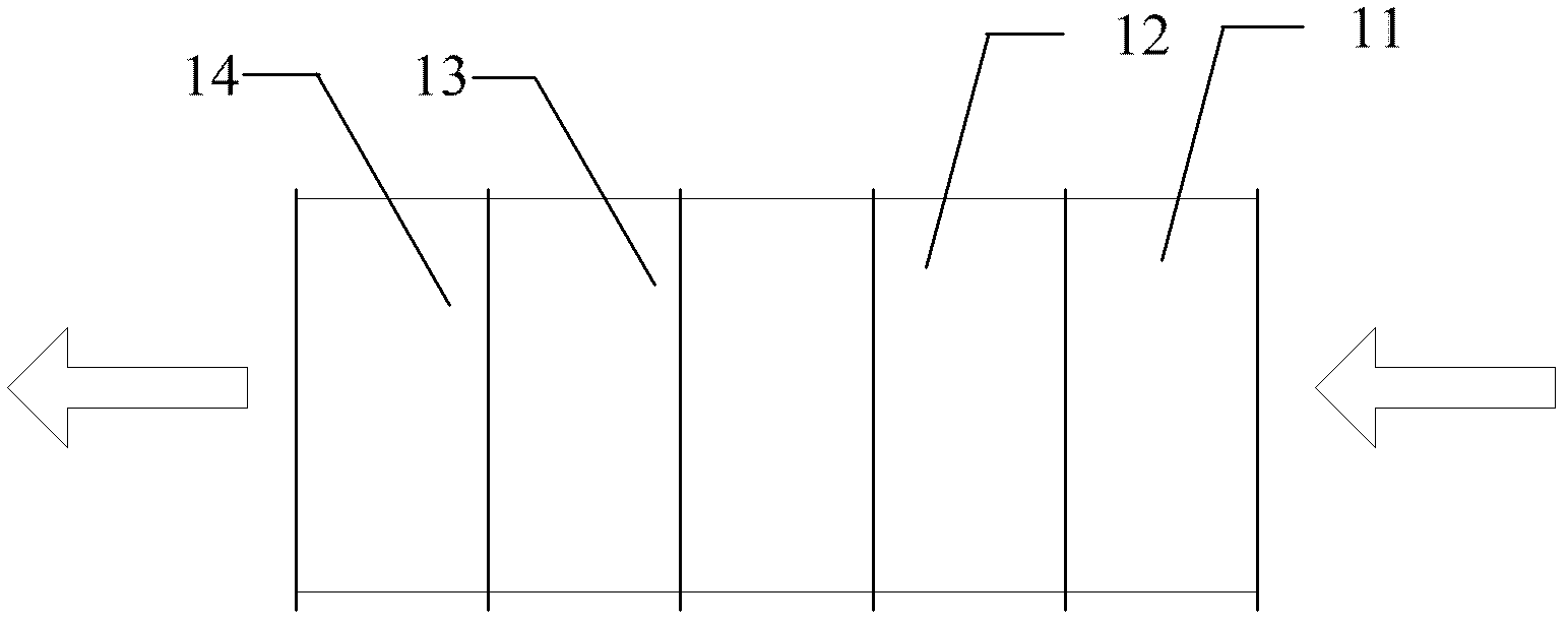
[0020] The structure of the cooling and humidity control system provided by the first embodiment of the present invention is as follows: figure 1 As shown, the system includes: a return air module 11 , a spray module 12 , a dehumidification module 13 and an air supply module 14 . The air outlet of the return air module 11 is connected to the air inlet of the spray module 12 , the air outlet of the spray module 12 is connected to the air inlet of the dehumidification module 13 through a ventilation duct, and the air outlet of the dehumidification module 13 is connected to the air inlet of the air supply module 14 . The return air module 11 and the air supply module 14 are installed with fans with appropriate air volume according to the ventilation volume requirements of the application site. The return air fan is installed in the return air module 11, and the air supply fan is installed in the air supply module 14. Install a high-pressure water pump with appropriate flow and se...

Embodiment 2

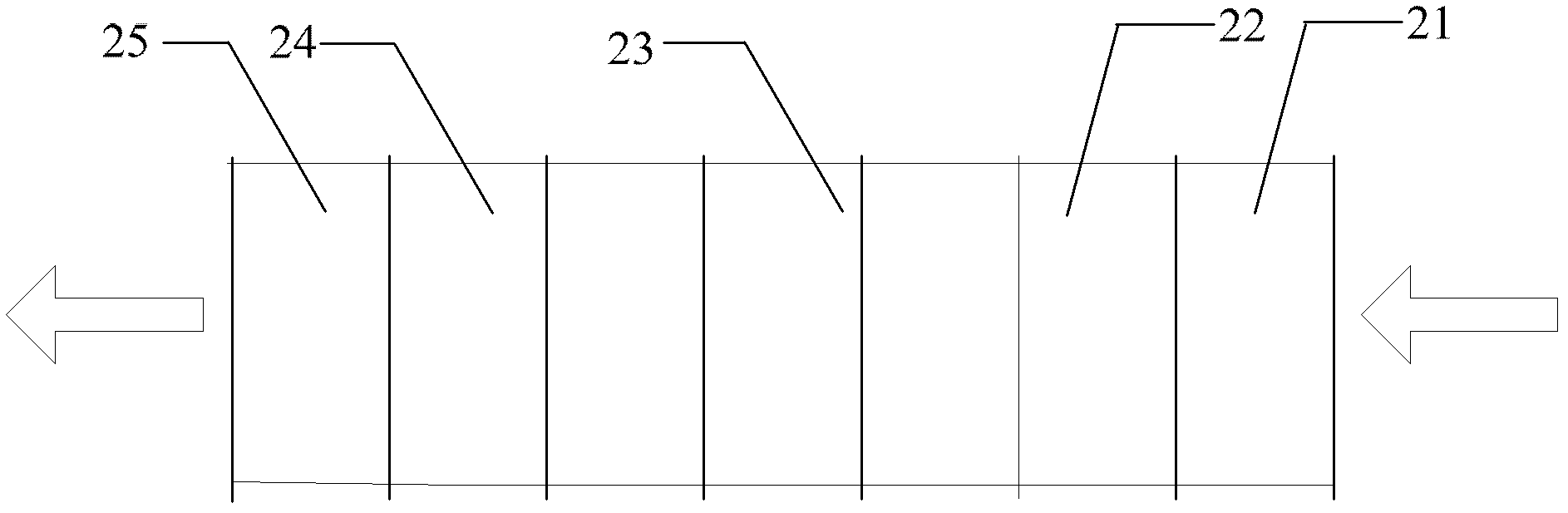
[0031] The structure of the cooling and humidity control system provided by the second embodiment of the present invention is as follows: figure 2 As shown, the system includes: a return air module 21 , a spray module 22 , a filter module 23 , a dehumidification module 24 and an air supply module 25 . The air outlet of the return air module 21 is connected to the air inlet of the spray module 22, the air outlet of the spray module 22 is connected to the air inlet of the filter module 23 through the ventilation duct, and the air outlet of the filter module 23 is connected to the air inlet of the dehumidification module 24 through the ventilation duct Connection, the air outlet of the dehumidification module 24 is connected to the air inlet of the air supply module 25 . The return air module 21 and the air supply module 25 are installed with fans of appropriate air volume according to the ventilation volume requirements of the application site. The return air fan is installed i...

Embodiment 3

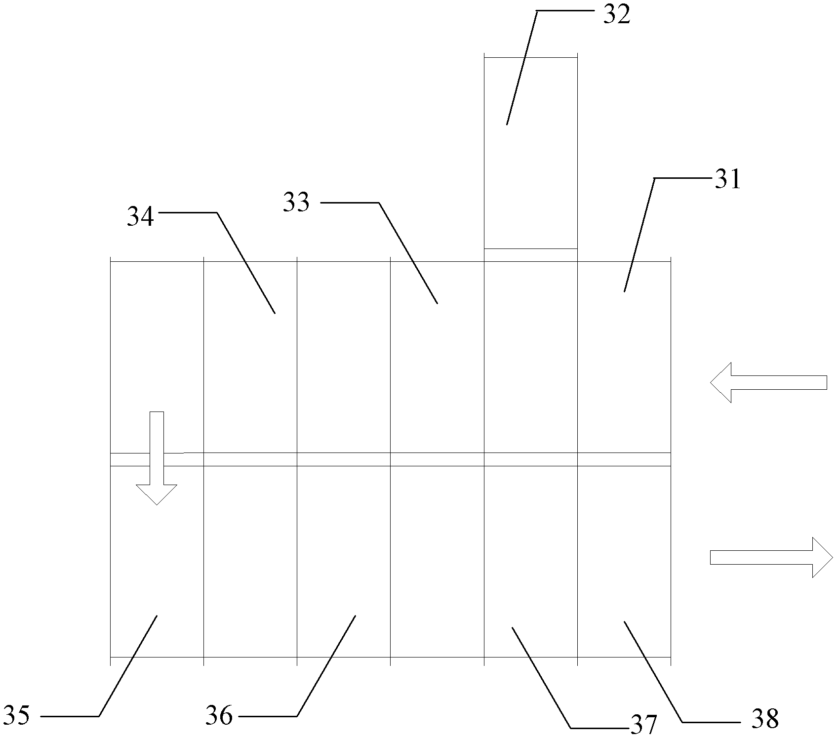
[0042] The structure of the cooling and humidity control system provided by the third embodiment of the present invention is as follows: image 3 As shown, the system includes: a return air module 31 , a fresh air module 32 , a spray module 33 , a filter module 34 , a filter module 35 , a dehumidification module 36 , a dehumidification module 37 and an air supply module 38 . The air outlet of the return air module 31 is connected to the air inlet of the spray module 33 through the ventilation duct, the air outlet of the spray module 33 is connected to the air inlet of the filter module 34 through the ventilation duct, and the air outlet of the filter module 34 is connected to the filter module 35 through the ventilation duct. The air inlet of the filter module 35 is connected with the air inlet of the dehumidification module 36 through the ventilation duct, the air outlet of the dehumidification module 36 is connected with the air inlet of the dehumidification module 37, and th...


PUM


Abstract

The invention discloses a cooling-down humidity-control system which comprises a return air module, an mist spraying module, a dehumidifying module and an air delivery module, wherein the air outlet of the return air module is connected to the air inlet of the mist spraying module; the air outlet of the air spraying module is connected to the air inlet of the dehumidifying module by a ventilating pipeline; and the air outlet of the dehumidifying module is connected to the air inlet of the air delivery module. The system further comprises a water storage tank and a system electric controller, wherein the return air module, the mist spraying module, the dehumidifying module and the air delivery module are respectively connected to the system electric controller; and the system electric controller controls the start and stop of each module. A fan is mounted in the return air module; a high-pressure water pump and a nozzle are mounted in the mist spraying module; a heat exchanger and a liquid nitrogen container are mounted in the dehumidifying module; and the liquid nitrogen container contains liquid nitrogen, which enters the heat exchanger after gasification. By using the cooling-down humidity-control system provided by the invention, not only can temperature and humidity be controlled, but also the system has low operation cost and is environmentally-friendly.

Description

technical field [0001] The invention relates to the technical field of cooling and humidity control, in particular to a cooling and humidity control system. Background technique [0002] At present, natural ventilation, forced ventilation, air conditioning and other solutions are mainly used for the dehumidification requirements of indoor environments such as workshops, equipment rooms, information rooms, and data centers. Natural ventilation and forced ventilation have poor cooling effect and are greatly affected by the environment, so they cannot control the temperature well. At the same time, natural ventilation and forced ventilation cannot control humidity. The cooling effect of the air conditioner is good, and it can control the humidity, but its operation cost is high, and the ozone-depleting gas and greenhouse gas will be generated during the operation. SUMMARY OF THE INVENTION [0003] The invention provides a cooling and humidity control system, which is used to...

Claims


Application Information

Patent Timeline
Patent Type & Authority Applications(China)
IPC IPC(8): F24F5/00F24F11/02F24F13/00
Inventor 王文生赵维森李骋虞贵斌
Owner 上海腾邦环境科技有限公司
Why Eureka
Try Eureka