Stabilizer for a utility vehicle

Inactive Publication Date: 2011-04-21
ZF FRIEDRICHSHAFEN AG
View PDF30 Cites 20 Cited by
  • Summary
  • Abstract
  • Description
  • Claims
  • Application Information

AI Technical Summary

Benefits of technology

[0005]Proceeding therefrom, the problem addressed by the invention is that of developing a stabilizer bar of the initially described type such that t

Problems solved by technology

The disadvantage of this system is that driving comfort is greatly reduced by the extreme roll of the driver's cab despite the anti-roll stabilization, in particular when travel takes place on poorly maintained, flat, and curvy roadways.
However,

Method used


Image

  • Stabilizer for a utility vehicle
  • Stabilizer for a utility vehicle
  • Stabilizer for a utility vehicle

Examples


Example

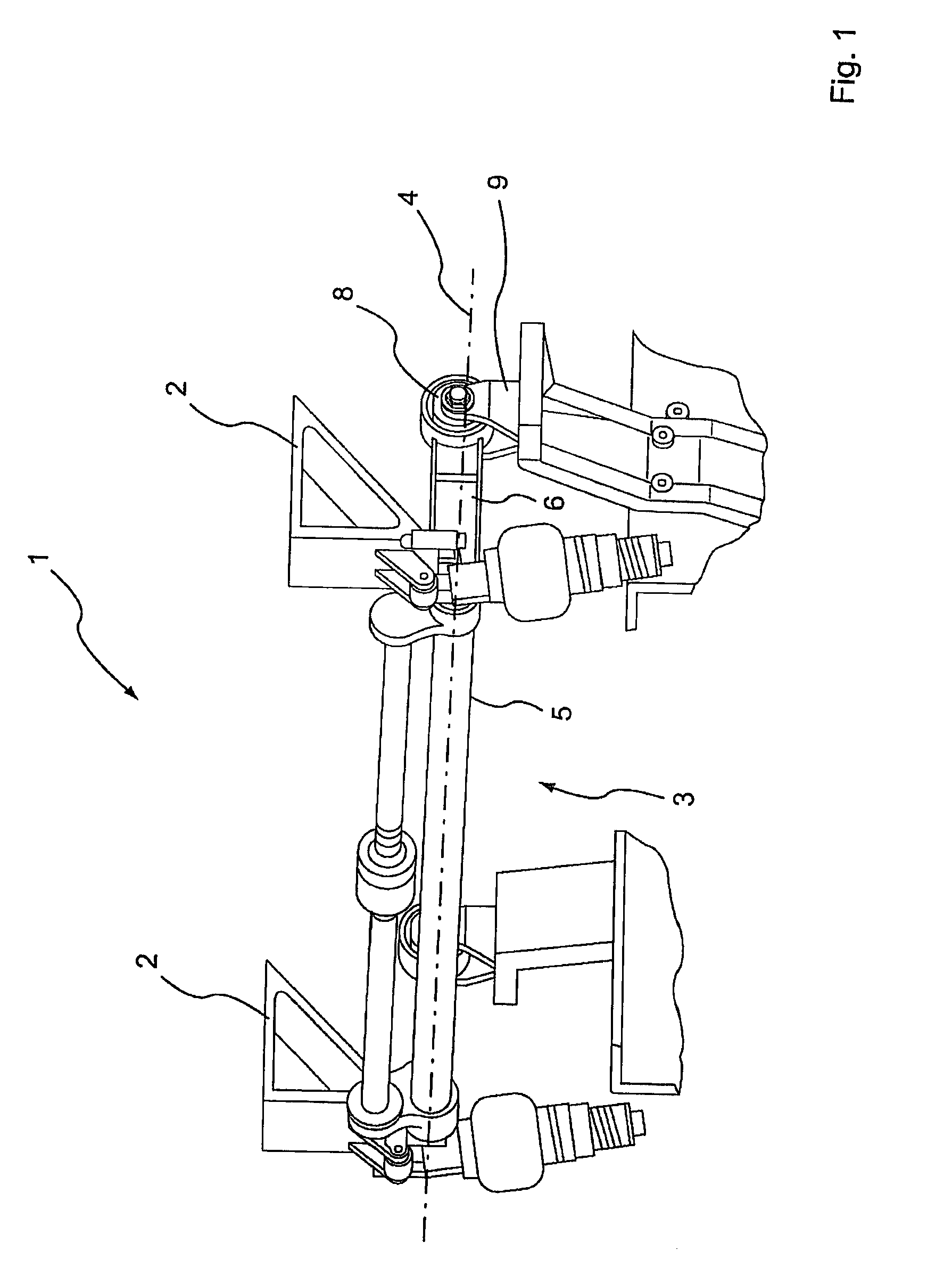
[0027]FIG. 1 shows a partially perspective view of a commercial vehicle 1 comprising a driver's cab 2, on which a stabilizer bar 3 according to a first embodiment of the invention is supported such that it can rotate about an axis 4. The stabilizer bar 3 comprises an elongated torsion spring 5, the longitudinal axis of which coincides with the axis 4. The suspension arms 6 and 7 (see FIG. 2) are connected to the ends of the torsion spring 5 in a rotationally fixed manner, and are connected to a vehicle frame 9 of the commercial vehicle 1 at a distance from the torsion spring 5 with rubber bearings 8 installed therebetween.

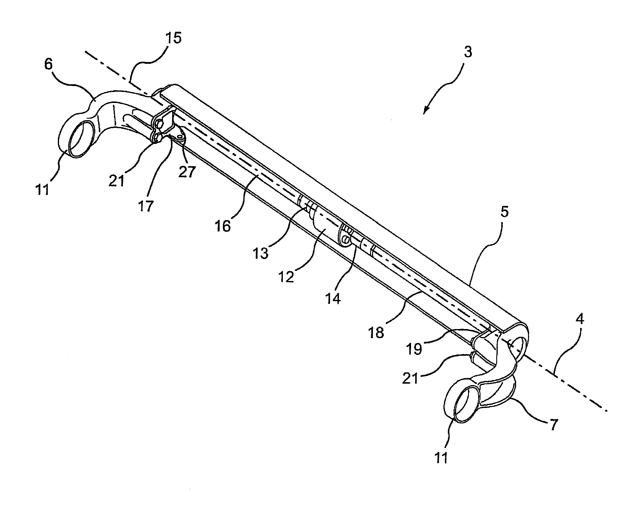
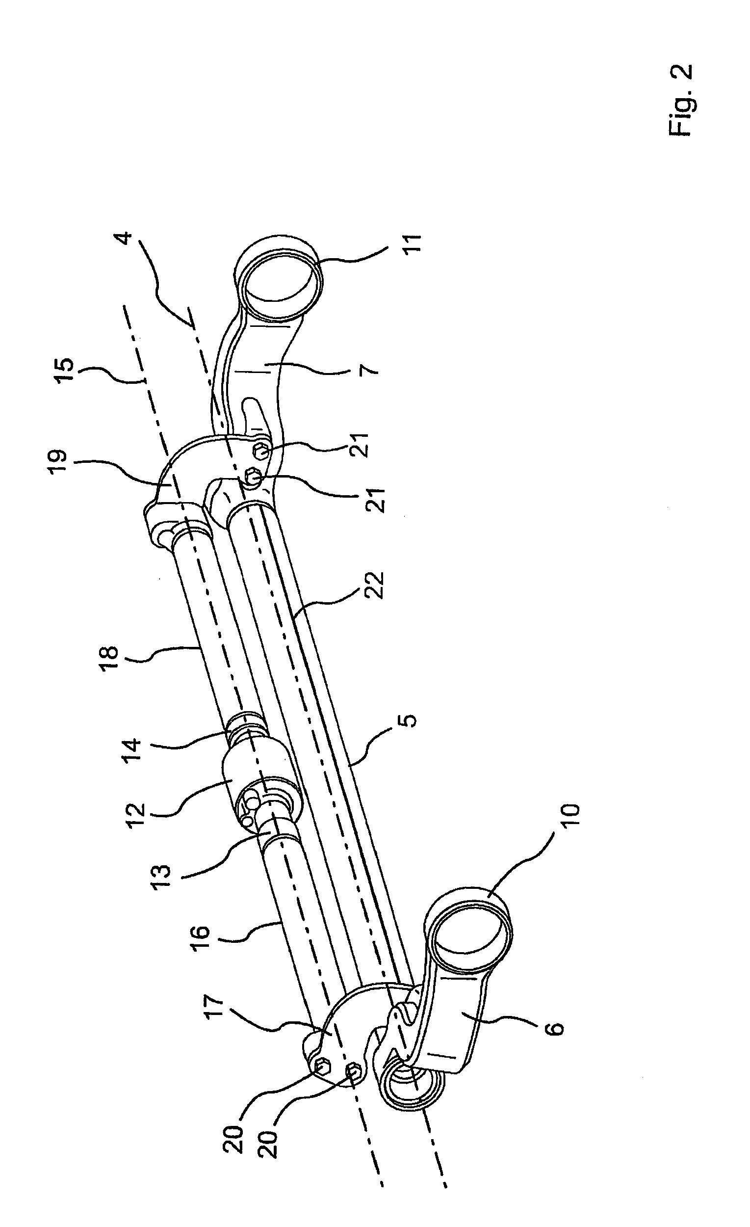
[0028]FIG. 2 shows a perspective illustration of the stabilizer bar 3 according to the first embodiment, wherein bearing seats 10 and 11 are formed on the ends of the suspension arms 6 and 7 facing away from the torsion spring 5 to accommodate the rubber bearings 8. The stabilizer bar 3 comprises an actuator 12 designed as a hydraulic oscillating motor which is use...


PUM


Abstract

A stabilizer bar for a commercial vehicle which comprises an elongate torsion spring (5), two suspension arms (6, 7) which are securely connected to and extend away from the torsion spring (5) and, between which the torsion spring (5) extends. An actuator (12) is connected in parallel with the torsion spring (5) and is connected to the torsion spring (5) or the suspension arms (6, 7) with the intermediate connection of hinge joints (23, 25) or leaf springs (17, 19).

Description

[0001]This application is a National Stage completion of PCT / DE2009 / 050030 filed Jun. 17, 2009, which claims priority from German patent application serial no. 10 2008 002 524.0 filed Jun. 19, 2008.FIELD OF THE INVENTION[0002]The invention relates to a stabilizer for a utility vehicle, comprising an elongated torsion spring and two suspension arms which are securely connected to the torsion spring and extend away therefrom, and between which the torsion spring extends.BACKGROUND OF THE INVENTION[0003]U.S. Pat. No. 4,648,620 discloses a stabilizer bar for a commercial vehicle that comprises a torsion spring bar, on each end of which an angled arm is disposed. The arms are connected by joints to a vehicle axle. The torsion spring bar extends through a two-piece torsion spring tube, the outer ends of which are welded to the torsion spring bar. The two parts of the torsion spring tube can be detachably interconnected using an actuatable coupling.[0004]In many commercial vehicles, the dr...

Claims


Application Information

Patent Timeline
IPC IPC(8): B60G21/055
CPCB60G17/0277B60G21/051B60G21/0555B60G2202/413B60G2202/442B62D33/0608B60G2204/162B60G2204/62B60G2206/201B60G2300/02B60G2204/1226
Inventor BUHL, MANFREDLANGHORST, FRIEDHELMEILERS, BERNHARD
Owner ZF FRIEDRICHSHAFEN AG
Why Eureka
Try Eureka