Motor drive controller and image forming apparatus incorporating the motor drive controller

a technology of motor drive controller and image forming apparatus, which is applied in the direction of motor/generator/converter stopper, dynamo-electric converter control, instruments, etc., can solve the problem of erroneous positional signal change cycle, prone to positioning error of constituting position detector, and increasing cos

Active Publication Date: 2011-04-21
RICOH KK
View PDF3 Cites 27 Cited by
  • Summary
  • Abstract
  • Description
  • Claims
  • Application Information

AI Technical Summary

Benefits of technology

[0011]Accordingly, an object of the present invention is to provide a new and novel motor drive controller. Such a new and novel motor drive controller controls rotation of a magnetic rotor of a motor by flowing periodic current through coils of plural phases. The motor drive controller includes a position detector that detects and outputs positional signals representing rotational positions of the magnetic rotor at first resolution, and a position change detector that detects and outputs position change signals representing positional changes of the magnetic rotor at second resolution higher than the first resolution. A phase syn

Problems solved by technology

Thus, a high-resolution encoder is necessarily arranged on a rotation shaft of the motor, thereby increasing cost.
However, a position detector, such as a Hall IC, etc., constituting the position detector is susceptible to error in positioning due to reflow mounting onto a print substrate.
If a changing point of

Method used


Image

  • Motor drive controller and image forming apparatus incorporating the motor drive controller
  • Motor drive controller and image forming apparatus incorporating the motor drive controller
  • Motor drive controller and image forming apparatus incorporating the motor drive controller

Examples


Embodiment Construction

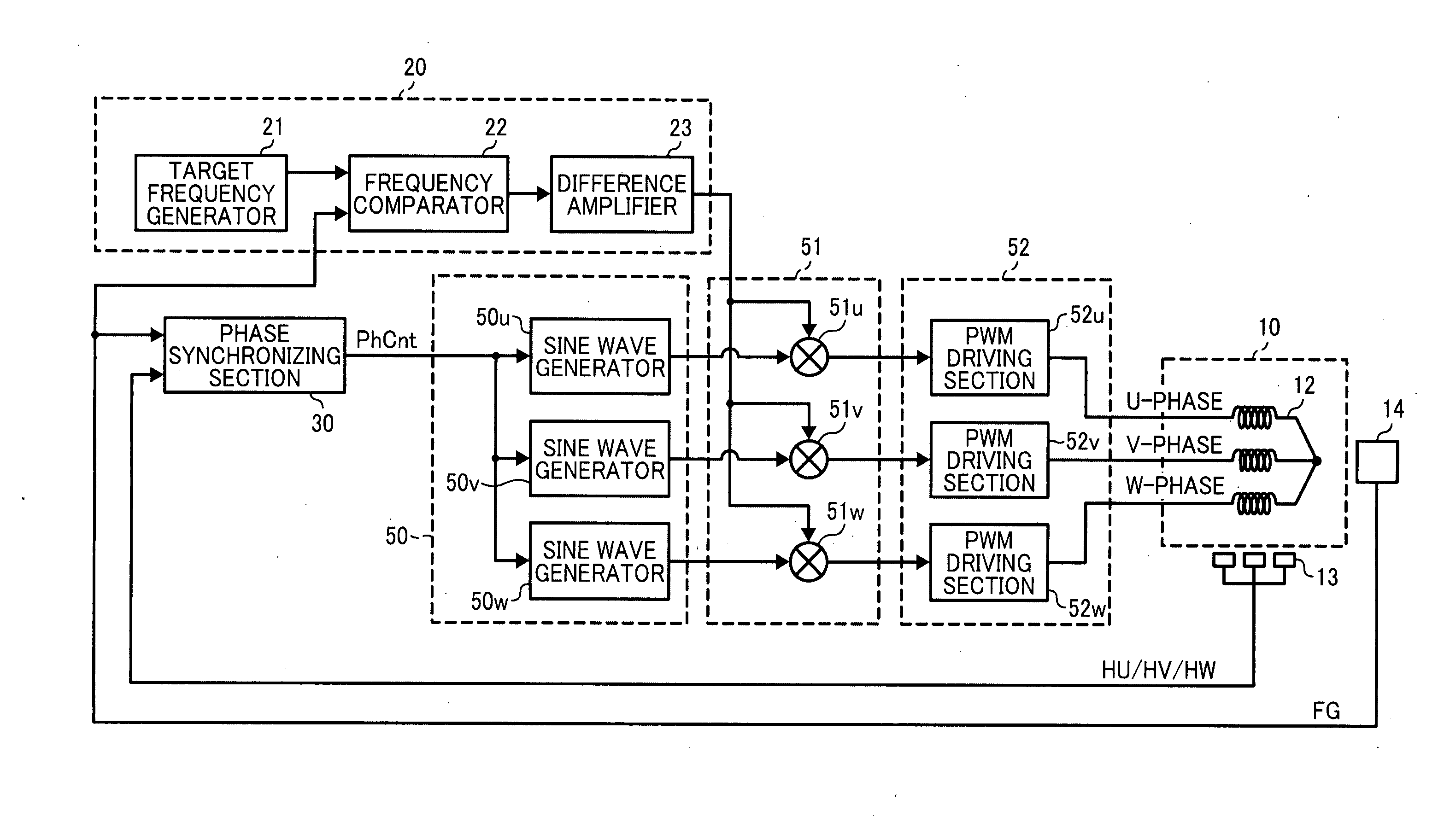
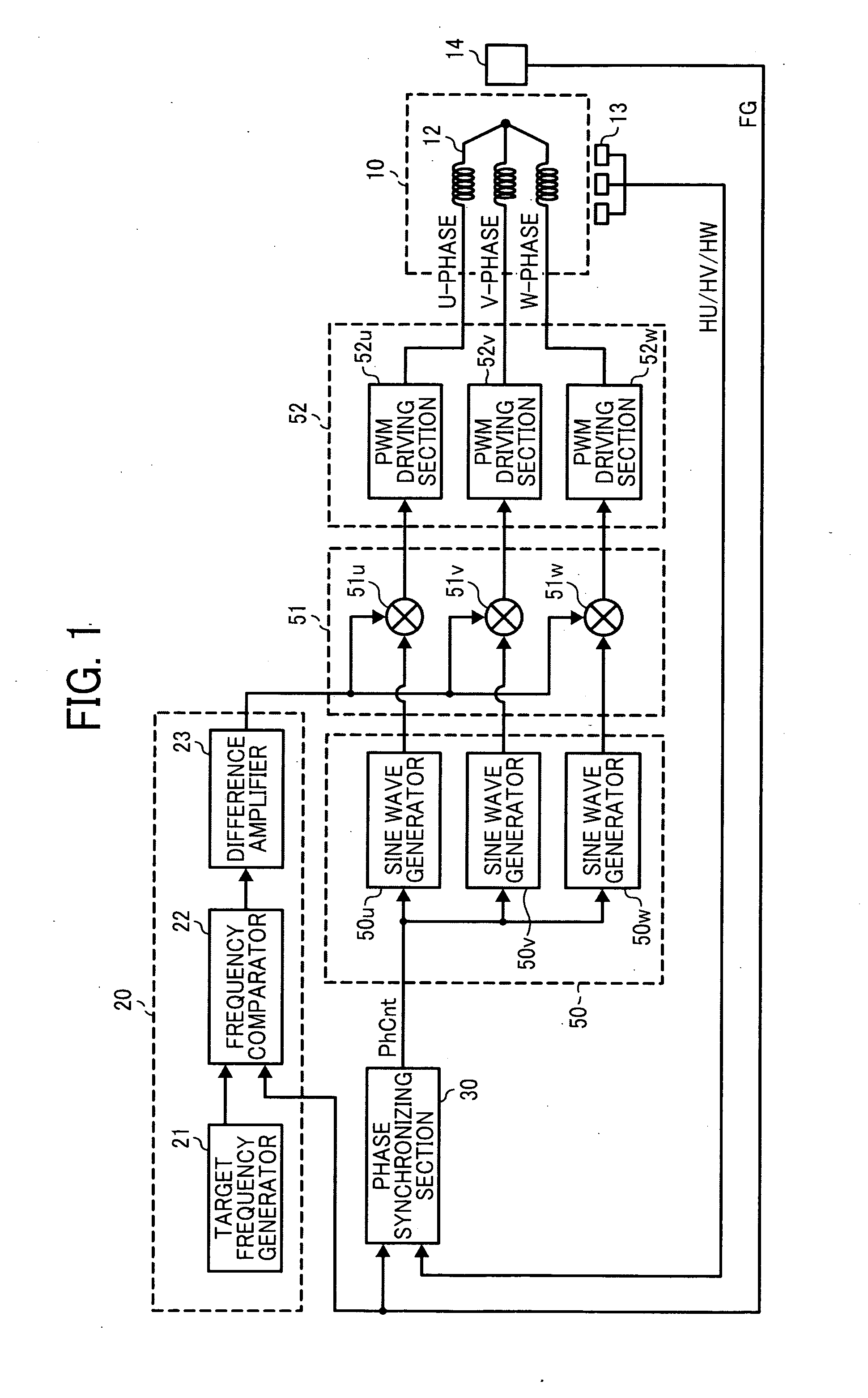
[0033]Referring now to the drawing, wherein like reference numerals designate identical or corresponding parts throughout several views, in particular in FIGS. 1 and 2, a non-brush motor 10 is provided and includes coils 12 of three phases of U, V and W wired in a Y-letter shape with a phase difference of 120 degree from each other.

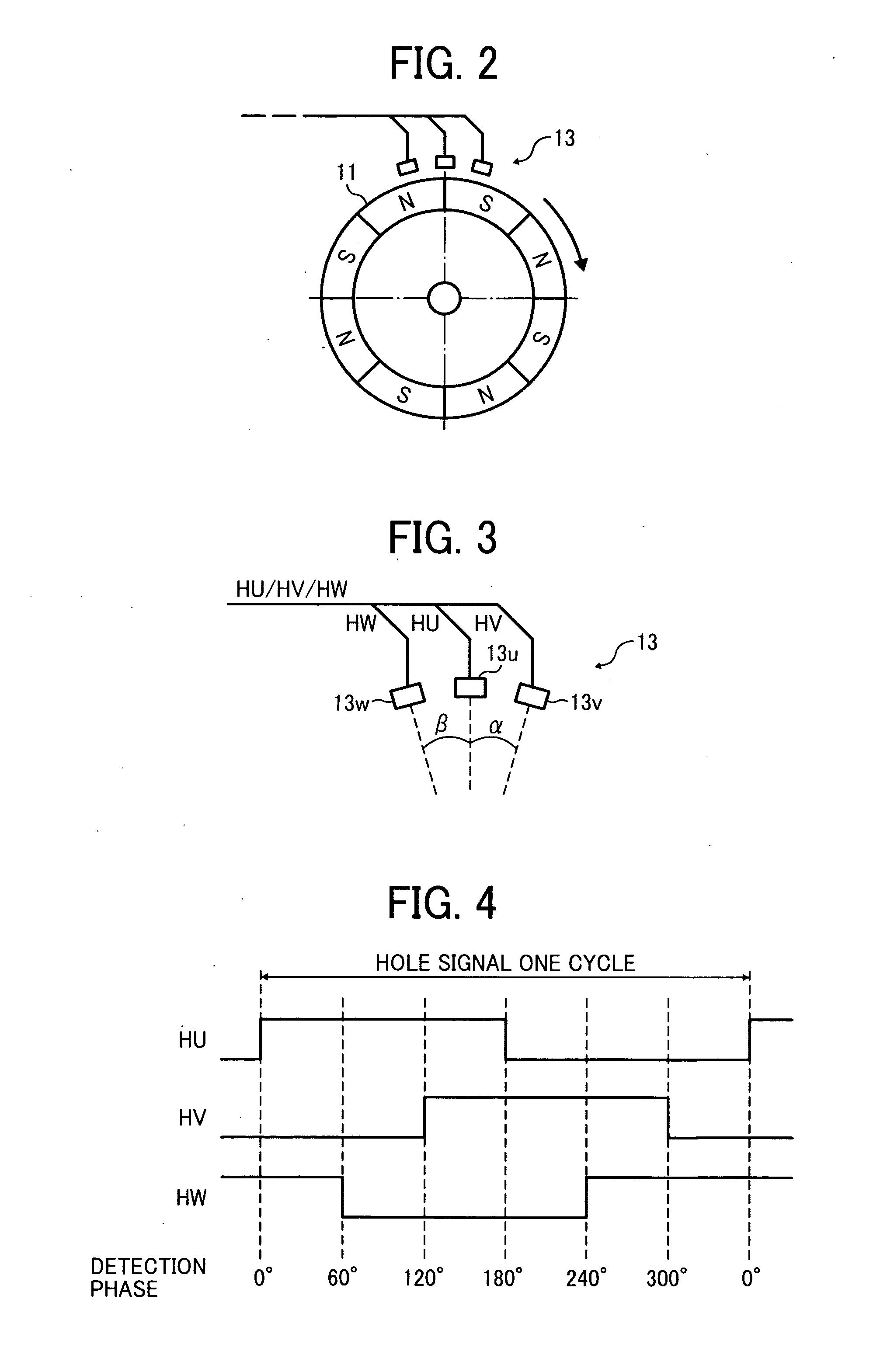
[0034]The non-brush motor 10 also includes a rotor 11 (not shown in FIG. 1) as permanent magnets having S and N poles alternately arranged while facing the coil 12 as shown in FIG. 2. The permanent magnets of the magnetic rotor 11 include eight poles.

[0035]A hall sensor 13 is provided as a position detector and includes three hall ICs 13u, 13v and 13w secured to the vicinity of the magnetic rotor 11 as shown in FIGS. 2 and 3. Each of the hall ICs is formed from a hall element and a hall amplifier as a package, and outputs binary hall signals HU, HV, or HW having a phase difference of 120 degree from the other in accordance with a change in a magnetic fiel...


PUM


Abstract

A motor drive controller includes a position detector that detects and outputs positional signals representing rotational positions of the magnetic rotor at first resolution, a position change detector that detects and outputs position change signals representing rotational positions of the magnetic rotor at second resolution higher than the first resolution, a phase synchronizing circuit that generates and outputs low resolution absolute phase information based on the positional and position change signals. The phase synchronizing circuit generates and outputs high-resolution absolute phase information based on the position change signals. A drive voltage signal outputting device outputs a drive voltage signal causing the current to flow through the coils in accordance with the absolute phase information.

Description

CROSS-REFERENCE TO RELATED APPLICATIONS[0001]This application claims priority pursuant to 35 USC §119 to Japanese Patent Application No. 2009-240277, filed on Oct. 19, 2009, the entire contents of which are hereby incorporated by reference herein.BACKGROUND OF THE INVENTION[0002]1. Field of the Invention[0003]The present invention relates to a motor drive controller capable of controlling rotary driving of a motor having coils of plural phases and an image forming apparatus incorporating the motor drive controller.[0004]2. Discussion of the Background Art[0005]In various fields, such as home appliances, office instruments, car electric generators, etc., non-brush motors are widely used. For example, a non-brush motor having coils of three phases arranged at phase intervals of 120 degrees is known that is equipped with a position detector to output positional signals that represent positions of a rotor by changing a signal level at every electrical angle of 60 degrees, and witch empl...

Claims


Application Information

Patent Timeline
IPC IPC(8): H02P6/16G03G21/00H02P6/06H02P6/08H02P6/17H02P6/28
CPCH02P6/16
Inventor SHIMIZU, FUMIHIRO
Owner RICOH KK
Why Eureka
Try Eureka