Inductive conversion device and energy control method

a conversion device and inductive technology, applied in the direction of dc-dc conversion, power conversion systems, instruments, etc., can solve the problems of energy exceeding the actual energy demand of the system, reducing and low conversion efficiency of converters, so as to improve the accuracy of energy estimation and effectively boost energy efficiency

Active Publication Date: 2011-04-21
ALPHA & OMEGA SEMICON CAYMAN
View PDF6 Cites 53 Cited by
  • Summary
  • Abstract
  • Description
  • Claims
  • Application Information

AI Technical Summary

Benefits of technology

[0015]This invention provides an inductive conversion device and energy control method that uses the error of output voltage to calculate the peak current of charging inductor and obtain the actual demand of total energy, thus effectively boosting the energy efficiency. The invention provides an inductive conversion device and energy control method that utilizes the fact that the total energy area corresponding to the output voltage error equals to the energy area of total energy required by the system to quantify the total energy required by the system based on output voltage error, thus improving the accuracy of energy estimation. The invention further provides an inductive conversion device and energy control method that can be applied in energy determination of various inductive conversion device circuit designs, thus provides extensive scope of application.

Problems solved by technology

However, charging the inductor with this reference current (IREF) as current threshold will result in energy exceeding the actual energy demand of the system, so the converter's energy effectiveness is not high.
However, although the method of forming a short-circuit path through free-wheeling switch can effectively solve the problem of energy exceeding the actual demand of the system by releasing the energy, the excessive energy is released through grounding in the process of energy release, thus rendering the energy effectiveness even more inferior than the technology disclosed in the above-mentioned U.S patent.

Method used


Image

  • Inductive conversion device and energy control method
  • Inductive conversion device and energy control method
  • Inductive conversion device and energy control method

Examples


Embodiment Construction

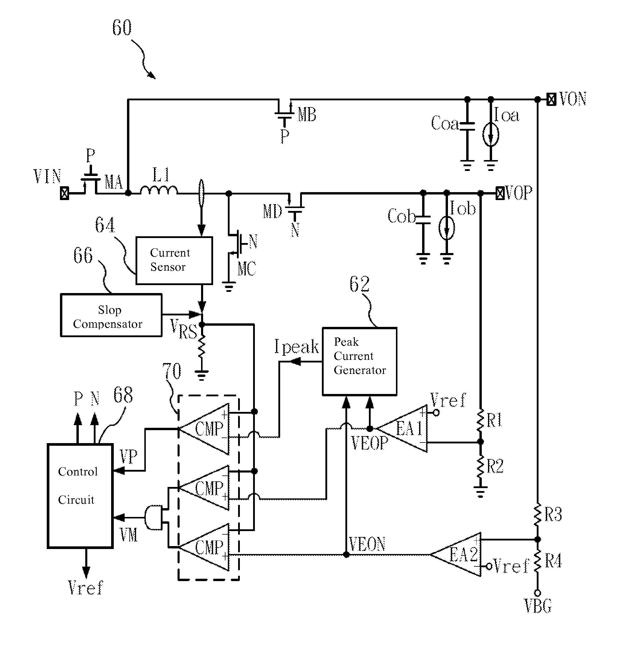
[0022]This invention discloses an inductive conversion device and energy control method, which obtains the up limit of charging current by calculating the peak current, thus knowing the total energy demand of the system. The following is a detailed description of the technical features of this invention with better implementation examples.

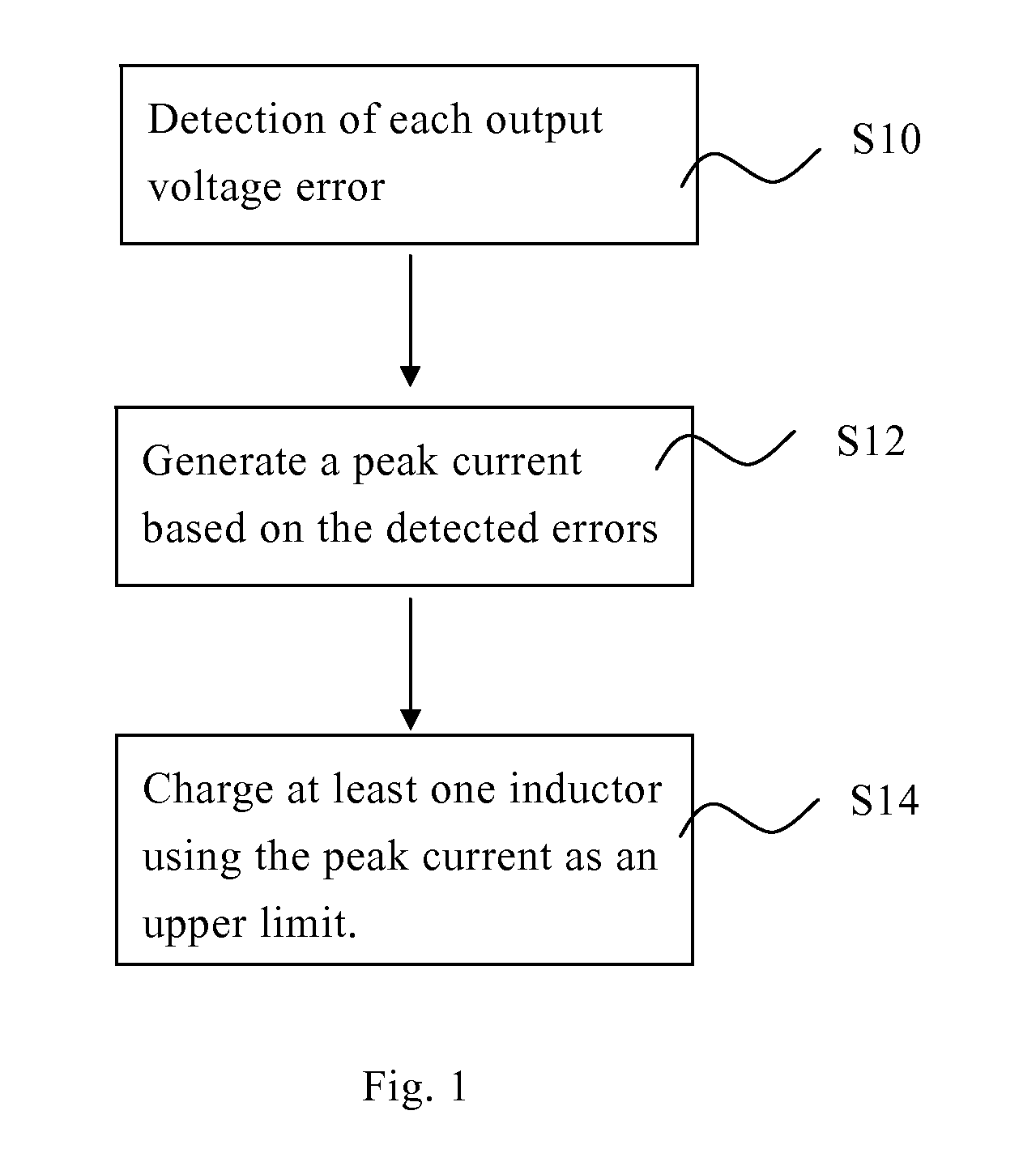
[0023]FIG. 1 is a flow chart of controlling inductive charging energy in this invention. As shown in the figure, firstly, as in Step S10, each individual error of a plurality of output voltages is measured. The output voltage can be either positive voltage or negative voltage of single-voltage output or multiple-voltage simultaneous output, and the error of the output voltage is calculated with a reference voltage as the basis. This reference voltage may be a fixed voltage dependent on the input voltage only and therefore independent of the switching cycles. Then, as in Step S12, a peak current is generated on the basis of the error of output volta...


PUM


Abstract

An energy control method for a inductive conversion device comprising: determination of individual error of multiple output voltages; determination of peak current based on the errors, determination of total energy through the peak current and charging to at least one inductor according to the peak current, whereas the inductor will store the total energy.

Description

[0001]This application is based upon and claims the foreign priority of a pending Taiwanese patent application filed on Oct. 20, 2009 with Taiwan App #98135387.TECHNICAL FIELD[0002]This invention relates to an electronic circuit device and energy effectiveness control method, especially an inductive conversion device and energy control method applied to power circuit conversion devices.BACKGROUND TECHNOLOGY[0003]Nowadays, many industrial applications and various electronic products have the design of power circuit, which will include a converter circuit, and the most common converter circuit will be equipped with an inductor. The U.S patent No. US2006 / 0114624, for example, proposes a converter system and control method with single inductor and multiple outputs, which feeds back the output voltage and dynamically generates reference current (IREF) through reference voltage generator and switching controller to control the inductor charging and discharging of the converter. However, c...

Claims


Application Information

Patent Timeline
Patent Type & Authority Applications(United States)
IPC IPC(8): G05F1/10
CPCH02M2001/009H02M3/1584H02M1/009
Inventor CHEN, KE-HORNGWU, JEAN-SHINTSAI, YU-NONGFAN, MING-YAN
Owner ALPHA & OMEGA SEMICON CAYMAN
Why Eureka
Try Eureka