
Damage-sensing composite structures

a composite structure and damage-sensing technology, applied in the field of fiber materials in composites, can solve the problems of crack initiation and propagation, composite structure is difficult to identify without the use of specialized equipment, and catastrophic failur

Inactive Publication Date: 2011-04-21
APPL NANOSTRUCTURED SOLUTIONS LLC
View PDF63 Cites 99 Cited by
  • Summary
  • Abstract
  • Description
  • Claims
  • Application Information

AI Technical Summary

Benefits of technology

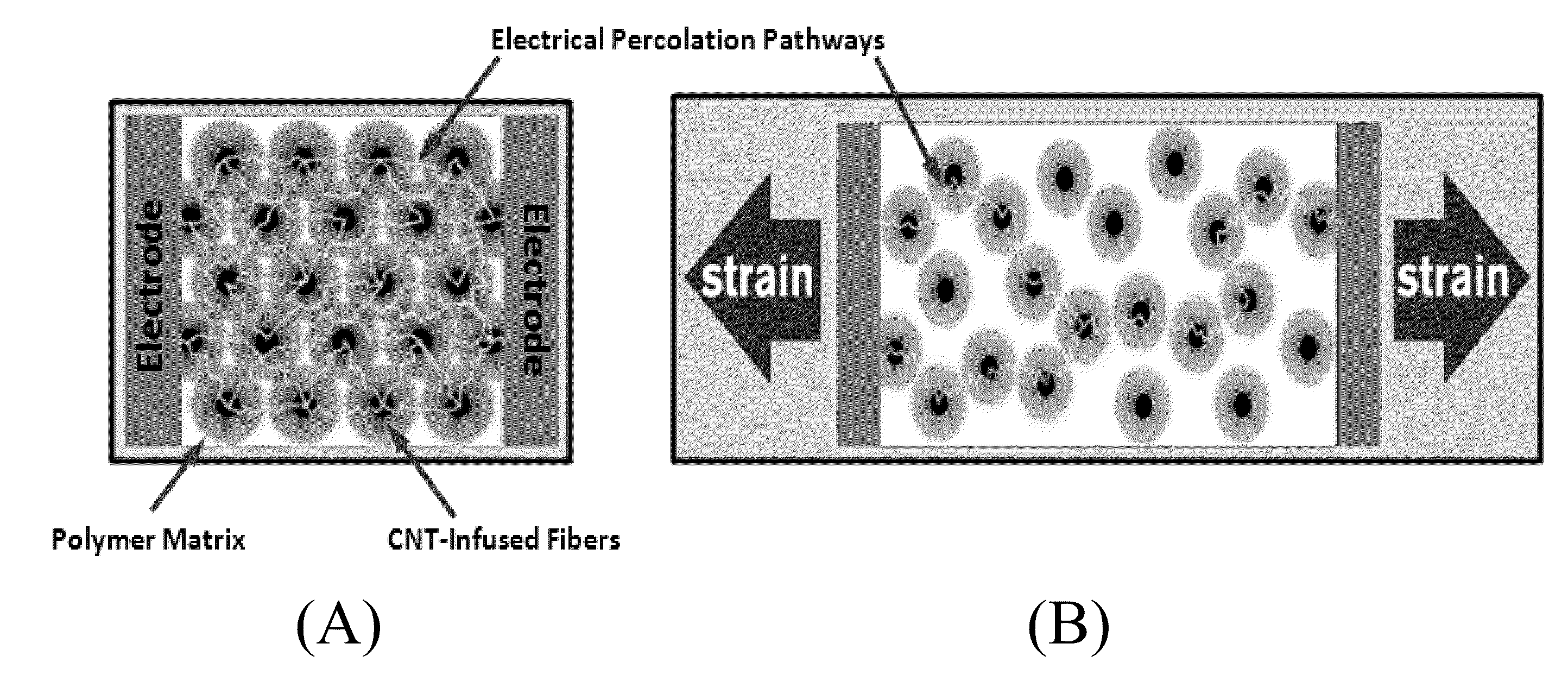
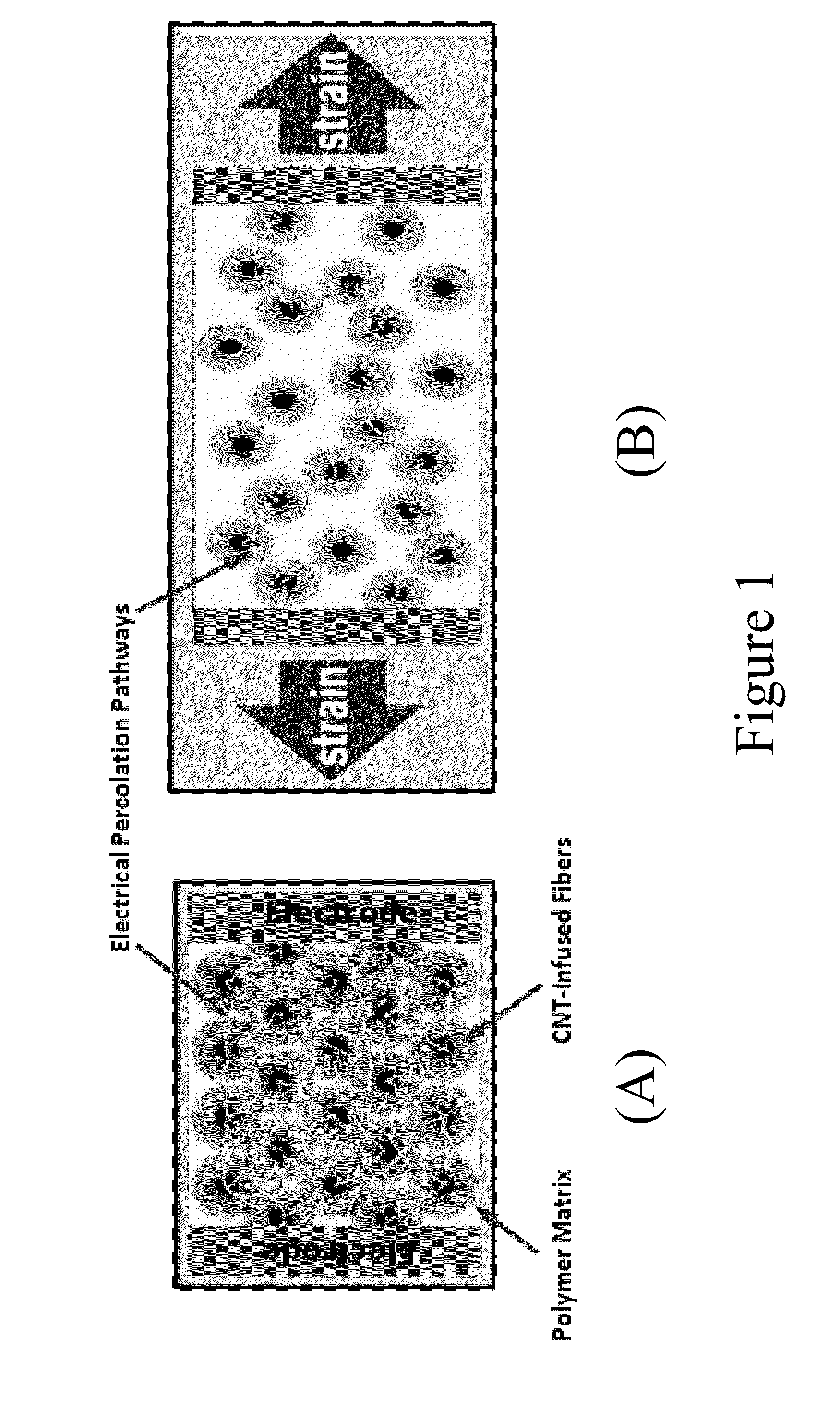
"The patent text describes a composite that includes a matrix material and a network of carbon nanotube-infused fibers. The composite can also have electrodes for sending and receiving an electrical charge. The system also includes sensing circuitry to detect changes in resistance across the composite caused by strain, fatigue, damage, or cracks. The technical effect of this invention is to provide a composite that can be used to detect and monitor changes in its structure and performance in real-time, which can help to improve its reliability and durability."

Problems solved by technology

Composites used in structural applications are susceptible to internal damage which can lead to catastrophic failure.
Crack initiation and propagation (as a result of high stress, impact, or fatigue) in composite structures is difficult to identify without the use of specialized equipment.

Method used


Image

  • Damage-sensing composite structures
  • Damage-sensing composite structures
  • Damage-sensing composite structures

Examples


example i

[0124]This example shows how a glass fiber material can be infused with CNTs in a continuous process and used in a ballistic damage sensing application. In this case, an array of short CNTs is desirable for enhanced damage detection resolution.

[0125]FIG. 14 depicts system 1500 for producing CNT-infused fiber in accordance with the illustrative embodiment of the present invention. System 1500 includes a glass fiber material payout and tensioner system 102, CNT-infusion system 112, and fiber winder 124, interrelated as shown.

[0126]Payout and tension system 102 includes payout bobbin 104 and tensioner 106. The payout bobbin holds fiber spools and delivers glass fiber material 101 to the process at a linespeed of 9 ft / min; the fiber tension is maintained within 1-5 lbs via tensioner 106. Payout and tension station 102 is routinely used in the fiber industry; those skilled in the art will be familiar with their design and use.

[0127]Tensioned fiber 105 is delivered to CNT-infusion system ...

example ii

[0136]This example shows how a glass fiber material can be infused with CNTs in a continuous process and used in a impact damage sensing application. In this case, an array of short CNTs is desirable for enhanced damage detection resolution.

[0137]FIG. 14 depicts system 1500 for producing CNT-infused fiber in accordance with the illustrative embodiment of the present invention. System 1500 includes a glass fiber material payout and tensioner system 102, CNT-infusion system 112, and fiber winder 124, interrelated as shown.

[0138]Payout and tension system 102 includes payout bobbin 104 and tensioner 106. The payout bobbin holds fiber spools and delivers glass fiber material 101 to the process at a linespeed of 12 ft / min; the fiber tension is maintained within 1-5 lbs via tensioner 106. Payout and tension station 102 is routinely used in the fiber industry; those skilled in the art will be familiar with their design and use.

[0139]Tensioned fiber 105 is delivered to CNT-infusion system 11...


PUM

PropertyMeasurementUnit
lengthaaaaaaaaaa
angleaaaaaaaaaa
diameteraaaaaaaaaa

Abstract

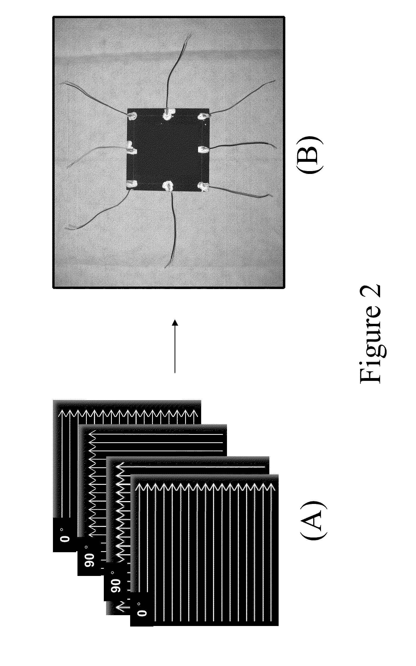
A composite includes a matrix material and a unidirectional array of carbon nanotube-infused fibers disposed in a portion of the matrix material. An article includes this composite and a network of electrodes disposed about the periphery of the composite. The electrodes send and receive an electrical charge. Such an article is included in a system, along with sensing circuitry and a source for supplying current to the network of electrodes. Such a system is used in a method that includes subjecting the article to a load that causes a condition in the composite including strain, fatigue, damage, or cracks, and monitoring the location of the condition.

Description

CROSS-REFERENCE TO RELATED APPLICATIONS[0001]This application claims the benefit of priority to U.S. Provisional Application Ser. No. 61 / 253,021, filed Oct. 19, 2009, the entire contents of which are incorporated herein by this reference.STATEMENT REGARDING FEDERALLY SPONSORED RESEARCH OR DEVELOPMENT[0002]Not applicable.FIELD OF THE INVENTION[0003]The present invention relates to fiber materials, more specifically to fiber materials in composites.BACKGROUND OF THE INVENTION[0004]Composites used in structural applications are susceptible to internal damage which can lead to catastrophic failure. Crack initiation and propagation (as a result of high stress, impact, or fatigue) in composite structures is difficult to identify without the use of specialized equipment. It would be beneficial to develop methods to monitor in situ damage of composite structures in various applications where identification of composite integrity is important to the system operation. The present invention sa...

Claims


Application Information

Patent Timeline
Patent Type & Authority Applications(United States)
IPC IPC(8): G01R27/08B32B3/00B32B17/12B32B27/04
CPCG01N27/20B82Y30/00Y10T428/249928Y10T428/249924Y10T428/24994B29K2105/124B29C70/14B29C70/882B29C70/081C01B32/00B32B5/02G01B7/16G01R27/08
Inventor MALECKI, HARRY C.HUGHES, JOHN ANTHONYSHAH, TUSHAR K.
Owner APPL NANOSTRUCTURED SOLUTIONS LLC
Learn More