System and method for inspecting a wind turbine blade

a wind turbine blade and blade technology, applied in the field of wind turbine blade inspection systems and methods, can solve the problems of more inspection time and costs, and the use of the probe on the surface of the wind turbine blade to measure defects,

Active Publication Date: 2011-04-21
GENERAL ELECTRIC CO
View PDF22 Cites 55 Cited by
  • Summary
  • Abstract
  • Description
  • Claims
  • Application Information

AI Technical Summary

Problems solved by technology

The use of the probe on the surfaces of the wind turbine blade to measure defects is a complex scanning process since the probe needs to follow the surface contour of the wind turbine blade and a couplant is required for ultrasound measurement of the wind turbine blade.
Moreover, each surface needs to be inspected separately, resulting in more inspection time and costs.

Method used


Image

  • System and method for inspecting a wind turbine blade
  • System and method for inspecting a wind turbine blade
  • System and method for inspecting a wind turbine blade

Examples


examples

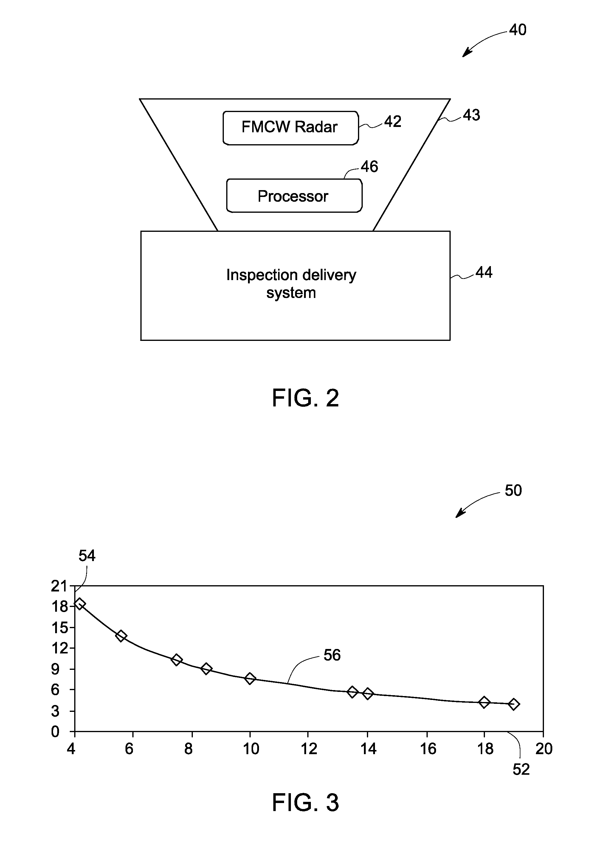
[0033]FIG. 10 is a graphical representation of FMCW radar data collected from a measurement depicting features that can be attributed to the pressure side and the suction side of the wind turbine blade (FIG. 1) in accordance with an embodiment of the invention. The FMCW radar data was collected from a single measurement in a lab scale test wherein a wind blade segment was kept stationary and an antenna was moved along the span and chord of the wind turbine blade segment. The single measurement depicts features that can be attributed to the pressure side and the suction side of the wind turbine blade. The X-axis 122 represents the time of flight of the microwave energy in nanoseconds. The Y-axis 124 represents the reflection coefficient of the microwave energy. The curve 126 represents variation of the reflected microwave energy as a function of travel time. This travel time, or time of flight, can be converted to the distance between the microwave inspection system and the wind turb...


PUM


Abstract

A wind turbine blade inspection system includes a frequency modulated continuous wave radar system configured to be movable with respect to a wind turbine blade while transmitting reference microwave signals and receiving reflected microwave signals and a processor configured for using a synthetic aperture analysis technique to obtain a focused image of at least a region of the wind turbine blade based on the reflected microwave signals.

Description

BACKGROUND[0001]The invention relates generally to wind turbines and more particularly to a system and method of inspecting a wind turbine blade.[0002]Wind turbines generate electricity from the kinetic energy of wind. Each wind turbine includes three major components: a structural support component, a generator component, and a rotor component. The rotor component further includes wind turbine blades that are employed to convert the kinetic energy of wind to mechanical energy which is then converted to electricity by the generator component.[0003]Inspection of wind turbine blades is important for ongoing operation of wind turbines. One method to inspect a wind turbine blade includes using an ultrasound probe to scan the surfaces of the wind turbine blade. The use of the probe on the surfaces of the wind turbine blade to measure defects is a complex scanning process since the probe needs to follow the surface contour of the wind turbine blade and a couplant is required for ultrasoun...

Claims


Application Information

Patent Timeline
Patent Type & Authority Applications(United States)
IPC IPC(8): G01S13/90
CPCF03D1/003F05B2260/80Y02E10/72G01S13/34G01S13/90G01N22/02F03D80/50G01S13/9088
Inventor TRALSHAWALA, NILESHFAIDI, WASEEM IBRAHIM
Owner GENERAL ELECTRIC CO
Why Eureka
Try Eureka