Lens shifter and projector using the same

a technology of shifter and projector, applied in the field of shifter, can solve the problems of increasing driving force and hindering smooth movement, and achieve the effect of increasing the strength of the rack and lowering the sliding resistan

Inactive Publication Date: 2011-04-21
SANYO ELECTRIC CO LTD
View PDF5 Cites 11 Cited by
  • Summary
  • Abstract
  • Description
  • Claims
  • Application Information

AI Technical Summary

Benefits of technology

[0019]The present invention relates to a lens shifter that lowers the sliding resistance produced at a rack, which transmits driving force in a horizontal direction or a vertical direction, while increasing the strength of the rack.

Problems solved by technology

This increases the driving force and hinders smooth movement.

Method used


Image

  • Lens shifter and projector using the same
  • Lens shifter and projector using the same
  • Lens shifter and projector using the same

Examples


first embodiment

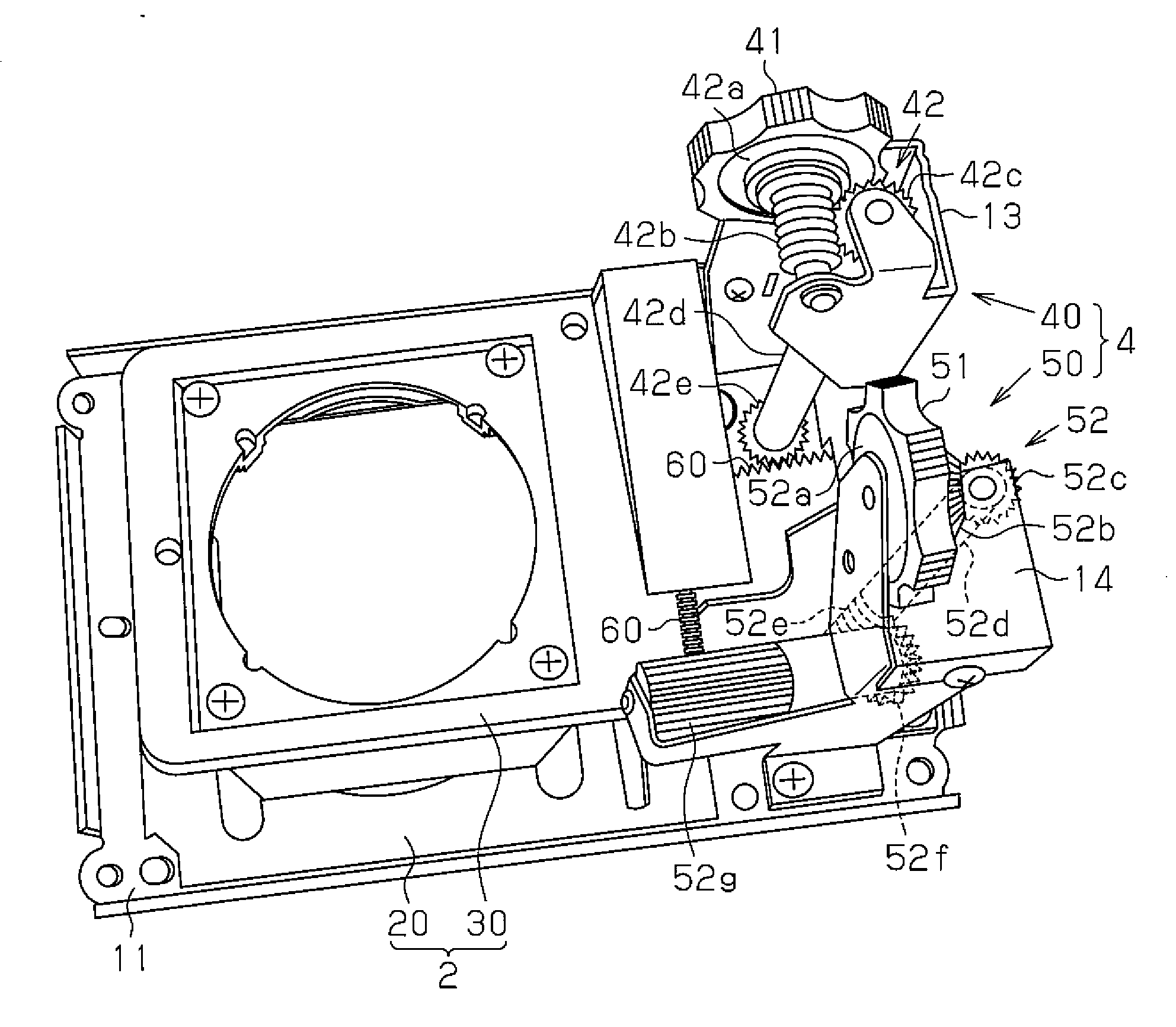
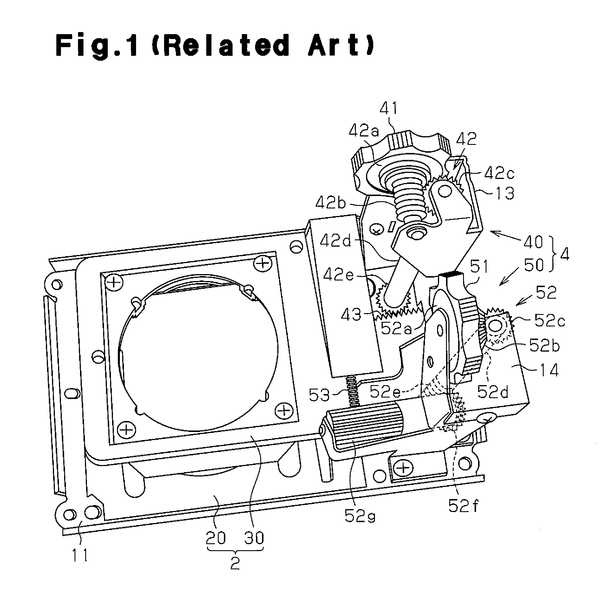
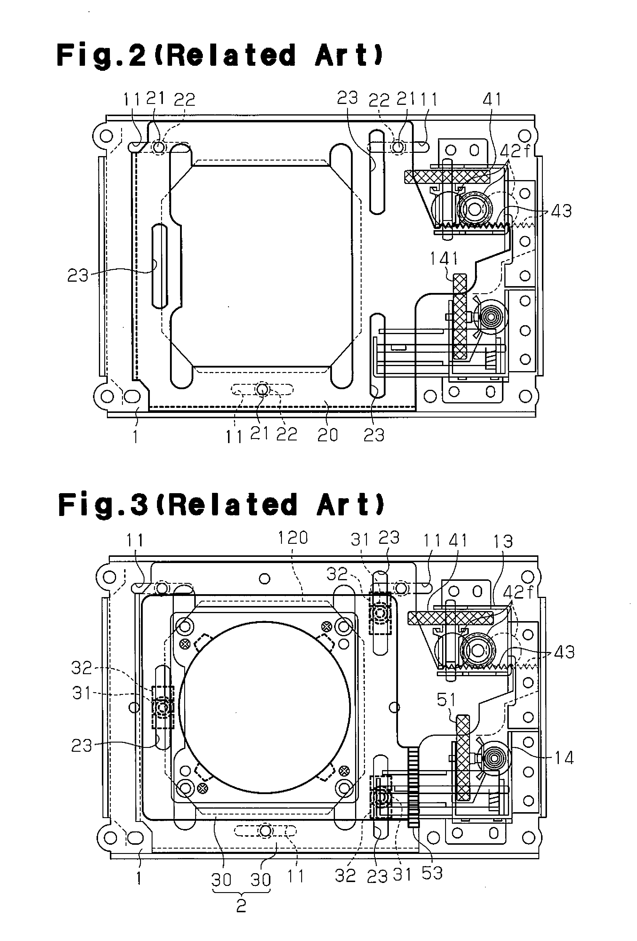
[0037]Referring to FIG. 4, in the first embodiment, the lens shifter includes a fixed base 1, a movable base 2, which is movable relative to the fixed base 1, and a drive mechanism 4, which applies a driving force to the movable base 2. The movable base 2 includes a horizontal movable base member 20, which is movable relative to the fixed base 1 in the horizontal direction, and the vertical movable base member 30, which is movable relative to the horizontal movable base member 20 in the vertical direction.

[0038]The drive mechanism 4 includes a horizontal drive mechanism unit 40, which drives the horizontal movable base member 20 in the horizontal direction, and a vertical drive mechanism unit 50, which drives the vertical movable base member 30 in the vertical direction. The horizontal drive mechanism unit 40 includes a driver 41, which generates force for driving the horizontal movable base member 20, a gear train 42, which transmits the force generated by the driver 41, and a firs...

second embodiment

[0050]A lens shifter according to the present invention will now be discussed with reference to FIGS. 7 to 9. In the description hereafter, the “horizontal direction” and the “vertical direction” respectively refer to the horizontal direction and vertical direction of the lens shifter when viewing the lens shifter from the front (from a position facing toward the projection lens).

[0051]Like the first embodiment, the lens shifter is used in a three-chip type LCD projector. As shown in FIG. 8, the lens shifter includes a fixed base 110, which is fixed to a unit chassis 101, a movable base 102, which is movable relative to the fixed base 110 in the vertical direction and the horizontal direction, and a drive mechanism 104, which moves the movable base 102. A projection lens is attached to the movable base 102.

[0052]Referring to FIG. 7, the fixed base 110 is fastened by a plurality of screws 111 to the unit chassis 101, which is fixed to a frame formed by walls projecting from a main bo...


PUM


Abstract

A lens shifter includes a fixed base and a movable base, which is movable relative to the fixed member and receives a projection lens. A drive mechanism applies driving force to the movable base. The drive mechanism includes a driver that generates force. A gear train transmits the force generated by the driver. A rack converts the force transmitted from the gear train into driving force for the movable base. The rack includes a tooth face extending along a tooth trace direction. A contact surface is formed only on part of the tooth face and receives the force from the gear train.

Description

CROSS-REFERENCE TO RELATED APPLICATIONS[0001]This application is based upon and claims the benefit of priority from prior Japanese Patent Application No. 2009-239273, filed on Oct. 16, 2009, the entire contents of which are incorporated herein by reference.BACKGROUND OF THE INVENTION[0002]The present invention relates to a lens shifter for an optical mechanism that shifts the position of a lens in a horizontal direction and / or vertical direction.[0003]A projector generally projects images onto a screen. Such a projector must project an image onto a screen at a predetermined position. Thus, a lens shifter is used to shift the position of a projection lens in a horizontal direction and / or a vertical direction to adjust the horizontal position and / or vertical position of the projected image.[0004]Japanese Laid-Open Patent Publication No. 2006-285260 describes such a lens shifter for a projector. The lens shifter of the publication will now be described with reference to FIGS. 1 to 3. I...

Claims


Application Information

Patent Timeline
Patent Type & Authority Applications(United States)
IPC IPC(8): G02B7/02
CPCG03B21/14G03B5/04G03B21/147
Inventor YOSHIMURA, TAICHI
Owner SANYO ELECTRIC CO LTD
Why Eureka
Try Eureka