Fuel cell system

a fuel cell and system technology, applied in the field of fuel cell systems, can solve problems such as shortening the fuel cell stack

Active Publication Date: 2011-04-21
TOYOTA JIDOSHA KK
View PDF7 Cites 10 Cited by
  • Summary
  • Abstract
  • Description
  • Claims
  • Application Information

AI Technical Summary

Benefits of technology

[0010]The invention provides technology that is able to inhibi...

Problems solved by technology

In such a fuel cell system, if electrical conduction is established between a high voltage portion of the fuel cell stack (such as a flow passage inside a separator that forms part of the fuel cell stack) and the circulating pump via water tha...

Method used


Image

  • Fuel cell system
  • Fuel cell system
  • Fuel cell system

Examples


first example embodiment

A. First Example Embodiment

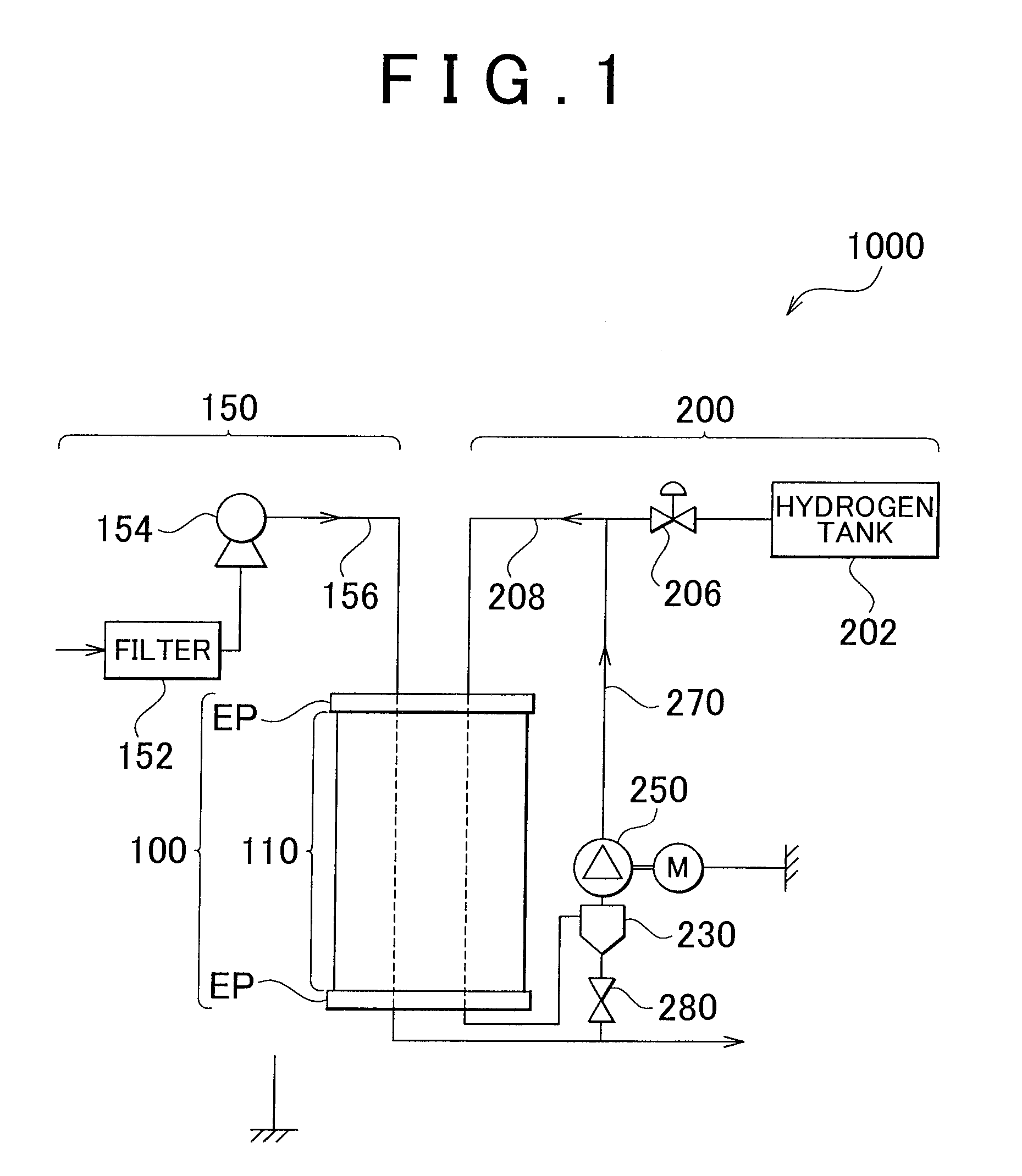
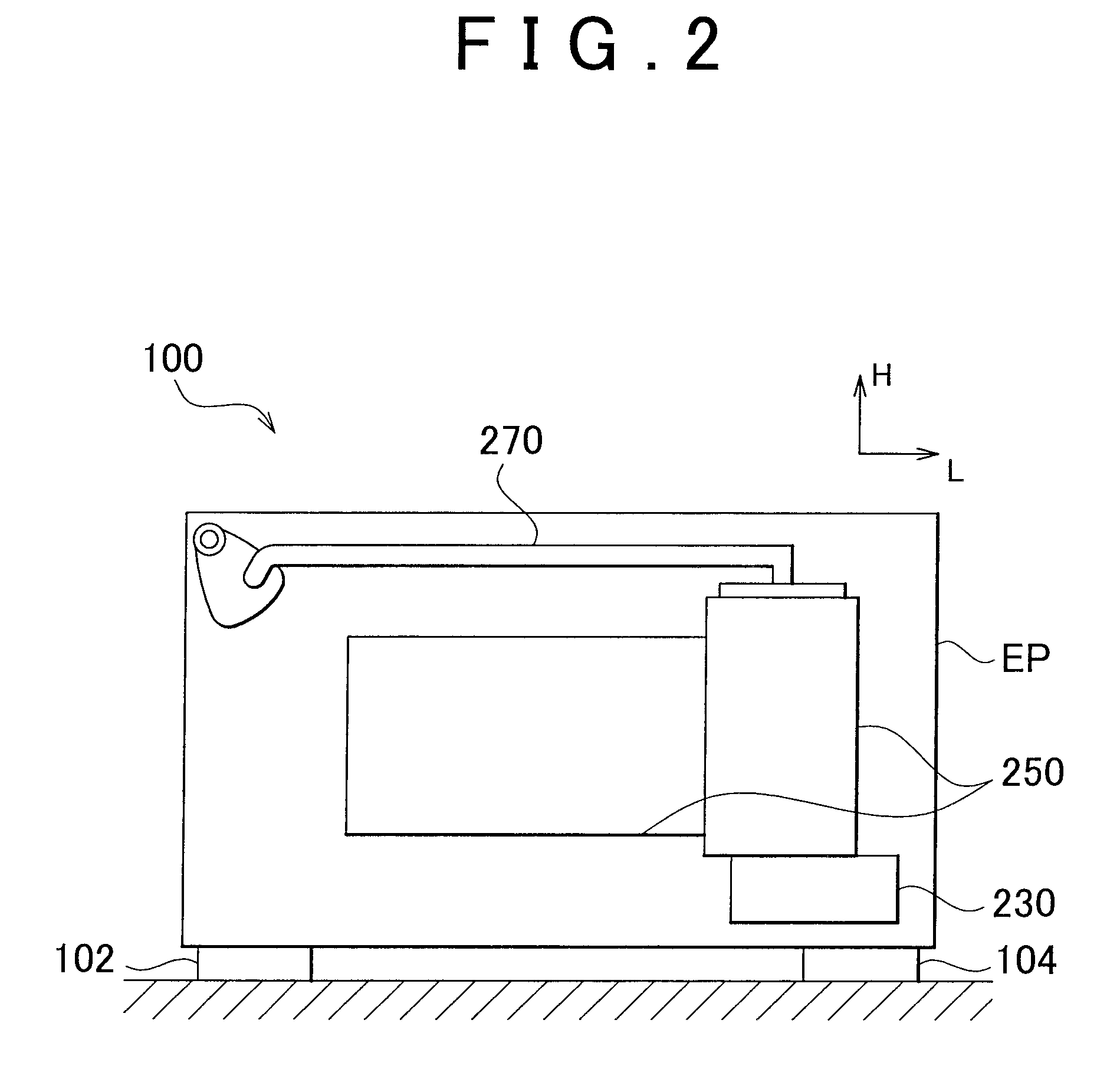
[0043]FIG. 1 is a view schematically showing the structure of a fuel cell system as a first example embodiment of the invention. The fuel cell system 1000 is a system that generates electricity using an electrochemical reaction between hydrogen and oxygen, and includes a fuel cell stack 100, an air supply system 150, and a fuel supply system 200. Incidentally, in this example embodiment, the fuel cell system 1000 for a fuel cell vehicle is used as an example, but the invention may also be applied to another fuel cell system such as a fixed fuel cell system.

[0044]The fuel cell stack 100 is formed by a stacked body 110 formed by a plurality of cells, not shown, that are stacked together, and two end plates EP that sandwich the stacked body 110. Each of the cells is formed by a separator, a fuel electrode (hereinafter referred to as an “anode”), an electrolyte membrane, an air electrode (hereinafter referred to as a “cathode”), and another separator stacked t...

second example embodiment

B. Second Example Embodiment

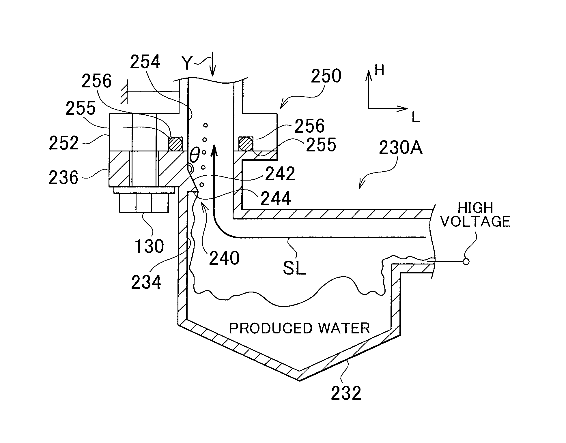
[0062]FIG. 5 is an enlarged view of the location where a gas-liquid separating device 230B and the hydrogen circulating pump 250 are connected together according to a second example embodiment of the invention. The only difference between the second example embodiment and the first example embodiment shown in FIG. 3A is that a mesh member 310 is arranged in the passageway of the passage portion 234, instead of having the protruding portion 240 formed on the passage portion 234 of the gas-liquid separating device 230B. Other than this, the structure is the same as it is in the first example embodiment. Incidentally, in this example embodiment, the mesh member 310 is fixed to the inside wall of the passage portion 234 by welding, but it may also be fixed to the passage portion 234 by fitting together with the passage portion 234.

[0063]The mesh member 310 has a mesh structure and may be made of resin such as nylon, or rubber or the like. The mesh structure o...


PUM


Abstract

A fuel cell system includes a fuel cell stack that generates electricity by an electrochemical reaction using a fuel gas; an insulating first passage member through which produced water that is produced by the electrochemical reaction in the fuel cell stack and off-gas that is discharged from the fuel cell stack pass; a conductive second passage member that is connected to the first passage member; and a produced water flow disrupting portion that is provided on the first passage member and breaks up or stops the flow of the produced water that is introduced from an inside wall of the first passage member to the second passage member.

Description

INCORPORATION BY REFERENCE[0001]The disclosure of Japanese Patent Application No. 2009-240037 filed on Oct. 19, 2010, including the specification, drawings and abstract is incorporated herein by reference in its entirety.BACKGROUND OF THE INVENTION[0002]1. Field of the Invention[0003]The invention relates to a fuel cell system.[0004]2. Description of the Related Art[0005]In recent years, vehicles provided with fuel cell systems have continued to be put into practical use. A fuel cell system typically has, in addition to a fuel cell stack that generates electricity by an electrochemical reaction between hydrogen and oxygen, a gas-liquid separating device that separates hydrogen off-gas discharged from the fuel cell stack from water produced by the electrochemical reaction in the fuel cell stack, and a circulating pump for supplying the hydrogen off-gas that has been separated from the water to the fuel cell stack again, and the like.[0006]The circulating pump in the fuel cell system ...

Claims


Application Information

Patent Timeline
IPC IPC(8): H01M8/06
CPCY02E60/50H01M8/04164
Inventor ITOGA, MICHITARO
Owner TOYOTA JIDOSHA KK
Why Eureka
Try Eureka