

Vehicle power transmission device
a transmission device and vehicle technology, applied in the direction of gearing details, transportation and packaging, gearing, etc., can solve the problems of not necessarily a sufficient solution of the problem, the difficulty of generating sufficient power in the lower rotation speed range of the drive source, and the deterioration of the fuel cost performance of the vehicle, so as to reduce the transmission of noise generated, prevent the durability of the case from deteriorating, and high rigidity
- Summary
- Abstract
- Description
- Claims
- Application Information
AI Technical Summary
Benefits of technology
Problems solved by technology
Method used
Image

Examples
first embodiment
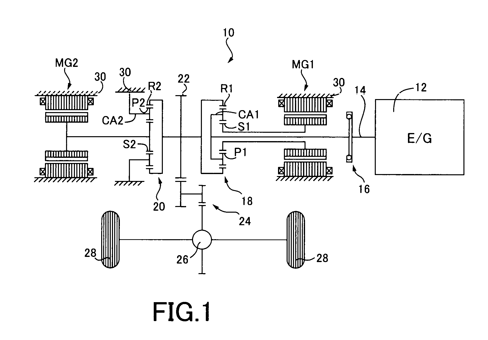
[0030]FIG. 1 is a schematic of a hybrid vehicle power transmission device 10 (hereinafter, power transmission device 10) to which the present invention is applied. As depicted in FIG. 1, the power transmission device 10 includes an engine 12, a first planetary gear device 18 acting as a power distribution mechanism coupled through a damper device 16 to a crankshaft 14 of the engine 12, a first electric motor MG1 coupled to the first planetary gear device 18 in a power transmissible manner, a second planetary gear device 20 as a reduction gear connected to the first planetary gear device 18, and a second electric motor MG2 coupled to the second planetary gear device 20 in a power transmissible manner.
[0031]The first electric motor MG1 and the second electric motor MG2 are so-called motor generators having a power generating function and the first electric motor MG1 acts as a differential electric motor for controlling a differential state of the power distribution mechanism 16 and at...
second embodiment
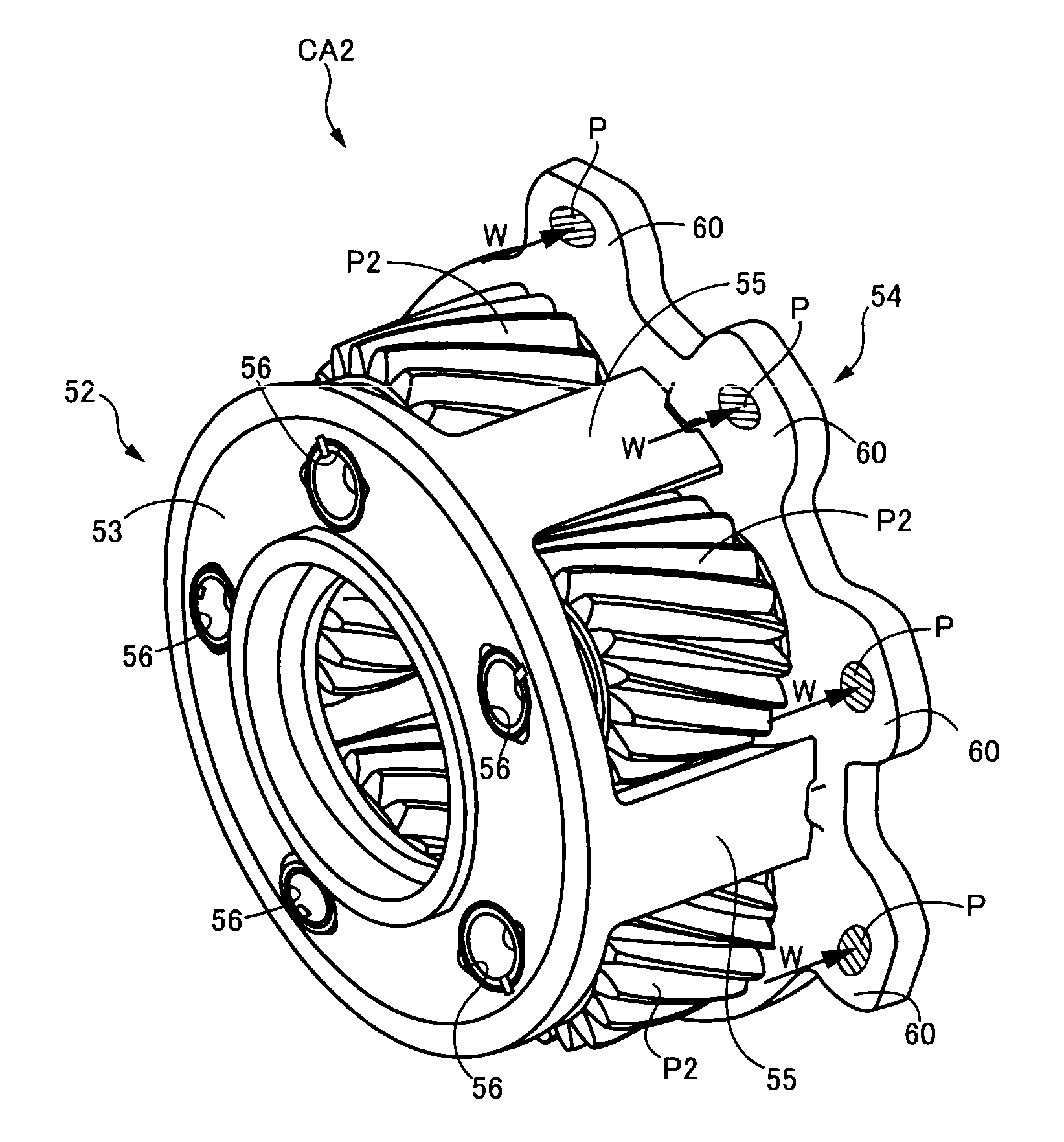
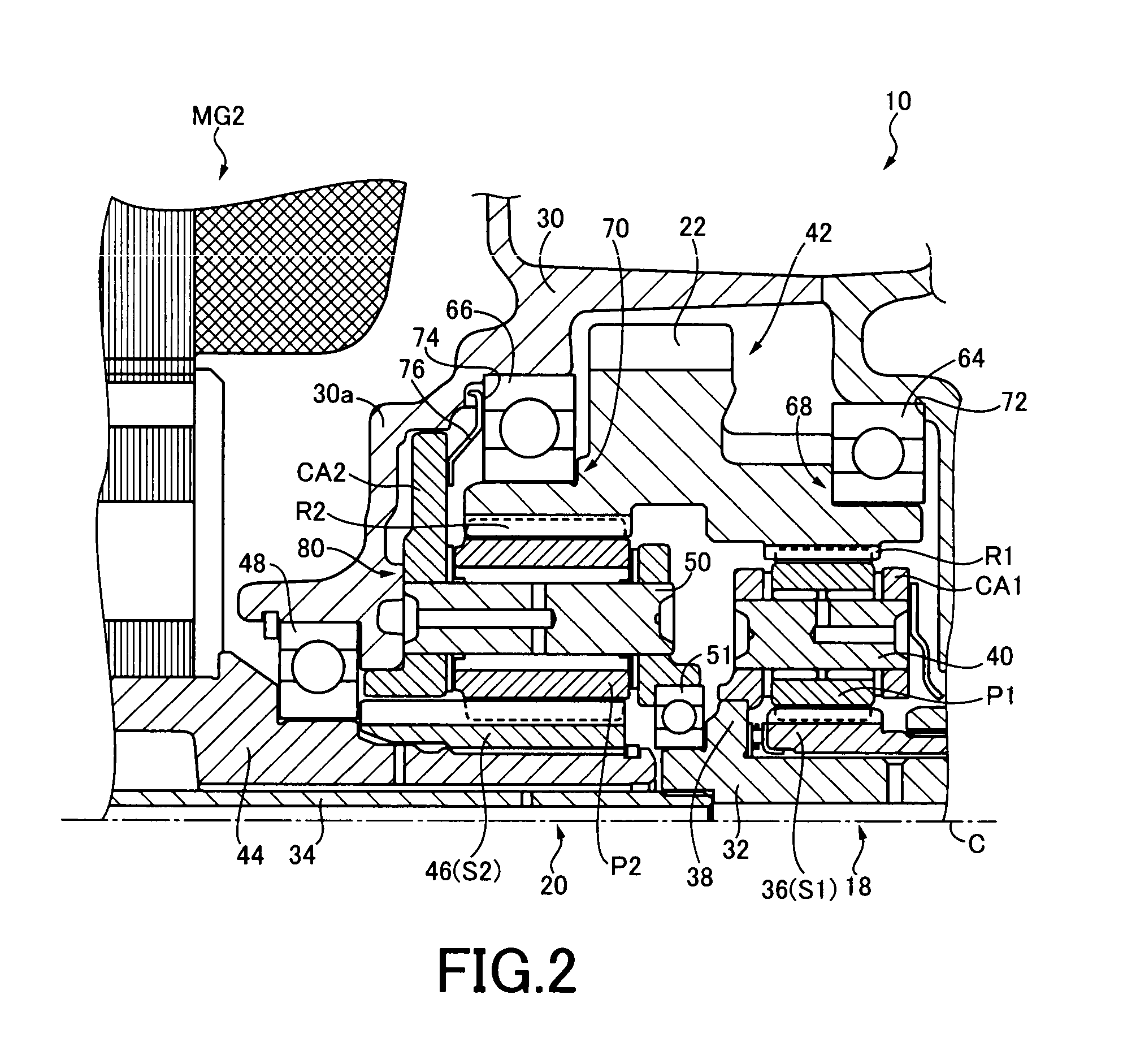
[0051]FIG. 6 is a cross-section view of a relevant portion of a power transmission device 100 of another embodiment of the present invention. In this embodiment, a spacer 102 (corresponding to the play reducing device of the present invention) is interposed between the carrier CA2 and the bearing 66 instead of the plate spring 76 acting as the play reducing device of the embodiment. The spacer 102 is an annular member made of metal, etc., and is interposed in abutment with the spline teeth 60 of the carrier CA2 and the end surface of the bearing 66. Since the interposing of the spacer 102 generates predetermined preload acting in the axial direction between the carrier CA2 and the bearing 66, the carrier CA2 is pressed toward the case 30 (the partition wall 30a) based on the preload and a play is reduced in the thrust direction between the carrier CA2 and the case 30. As the carrier CA2 and the case 30 are pressed by the preload, the rotational fluctuations are suppressed (in other ...
third embodiment
[0054]FIG. 7 is a cross-section view of a relevant portion of a power transmission device 104 of yet another embodiment of the present invention. In this embodiment, an elastic member 106 (corresponding to the play reducing device of the present invention) made of, for example, rubber material is interposed as the play reducing device between the carrier CA2 and the bearing 66. The elastic member 106 is interposed in a compressed state in abutment with the spline teeth 60 of the carrier CA2 and the end surface of the bearing 66, generating predetermined preload (elastic restoring force) acting in parallel with the shaft center. Therefore, the carrier CA2 is pressed against the case 30 (the partition wall 30a) based on the preload and a play is reduced in the thrust direction between the carrier CA2 and the case 30. As the carrier CA2 and the case 30 are pressed by the preload, the rotational fluctuations are suppressed (in other words, the spline play is suppressed) in the circumfer...
PUM
 Abstract
Description
Claims
Application Information