Duct Smoke Detection System and Method

a smoke detection system and duct technology, applied in the field of duct smoke detection system and method, can solve the problems of multiple duct mounted smoke detectors on the supply side that are difficult to test, duct mounted smoke detectors that are dirty from the test smoke, and need to be cleaned, so as to reduce the amount of test smoke entering the duct, reduce labor, and reduce the effect of building temperature chang

Active Publication Date: 2011-04-28
TOWNSEND ROBERT L +1
View PDF4 Cites 21 Cited by
  • Summary
  • Abstract
  • Description
  • Claims
  • Application Information

AI Technical Summary

Benefits of technology

[0012]Advantages of the present invention include the ability to limit the amount of test smoke entering the duct. Another advantage is that testing of the ductwork mounted smoke detectors can be accomplished quickly, which means less labor and less temperature change in the building. A further advantage is that the testing is very simple, enabling building owners to test the smoke detectors themselves. These and other advantages will be apparent to those skilled in the art based on the disclosure set forth herein.

Problems solved by technology

Testing of duct-mounted smoke detectors located on the air handler supply ductwork is difficult.
Multiple duct mounted smoke detectors on the supply side are very difficult to test because duct mounted smoke detectors located downstream of other duct mounted smoke detectors will sample the test smoke laden air and shut down the air handler and the test smoke does not reach the duct mounted smoke detector desired to be tested.
Because great quantities of test smoke is running through the duct work the duct mounted smoke detectors become dirty from the test smoke and need to be cleaned to stop alarming.
The tests are scheduled during unoccupied building use times because the air handler systems of the building are not conditioning the air in the building properly because they are being shutdown and also because the test smoke used to test the duct mounted smoke detectors has traveled throughout the whole building.

Method used


Image

  • Duct Smoke Detection System and Method
  • Duct Smoke Detection System and Method
  • Duct Smoke Detection System and Method

Examples


Embodiment Construction

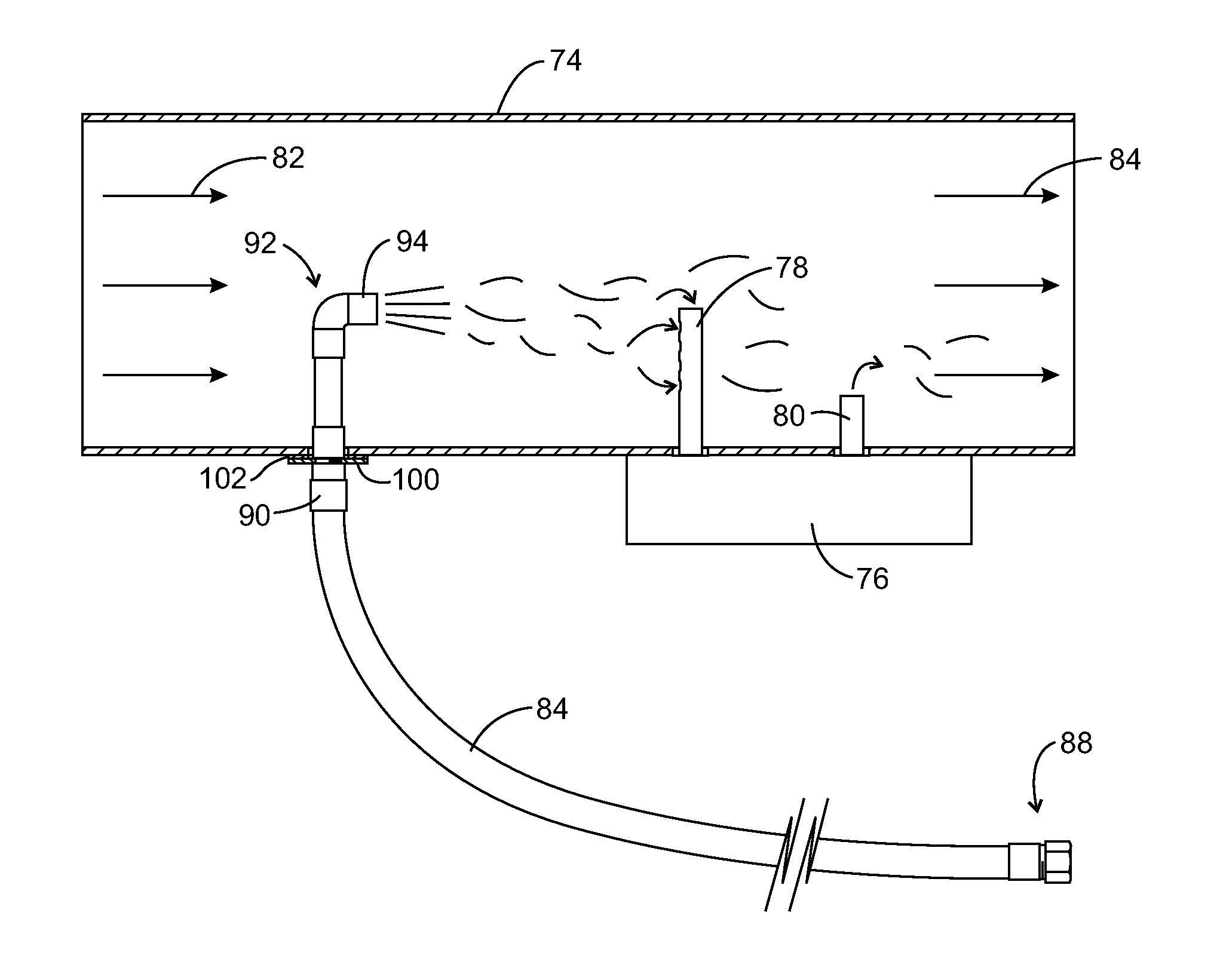
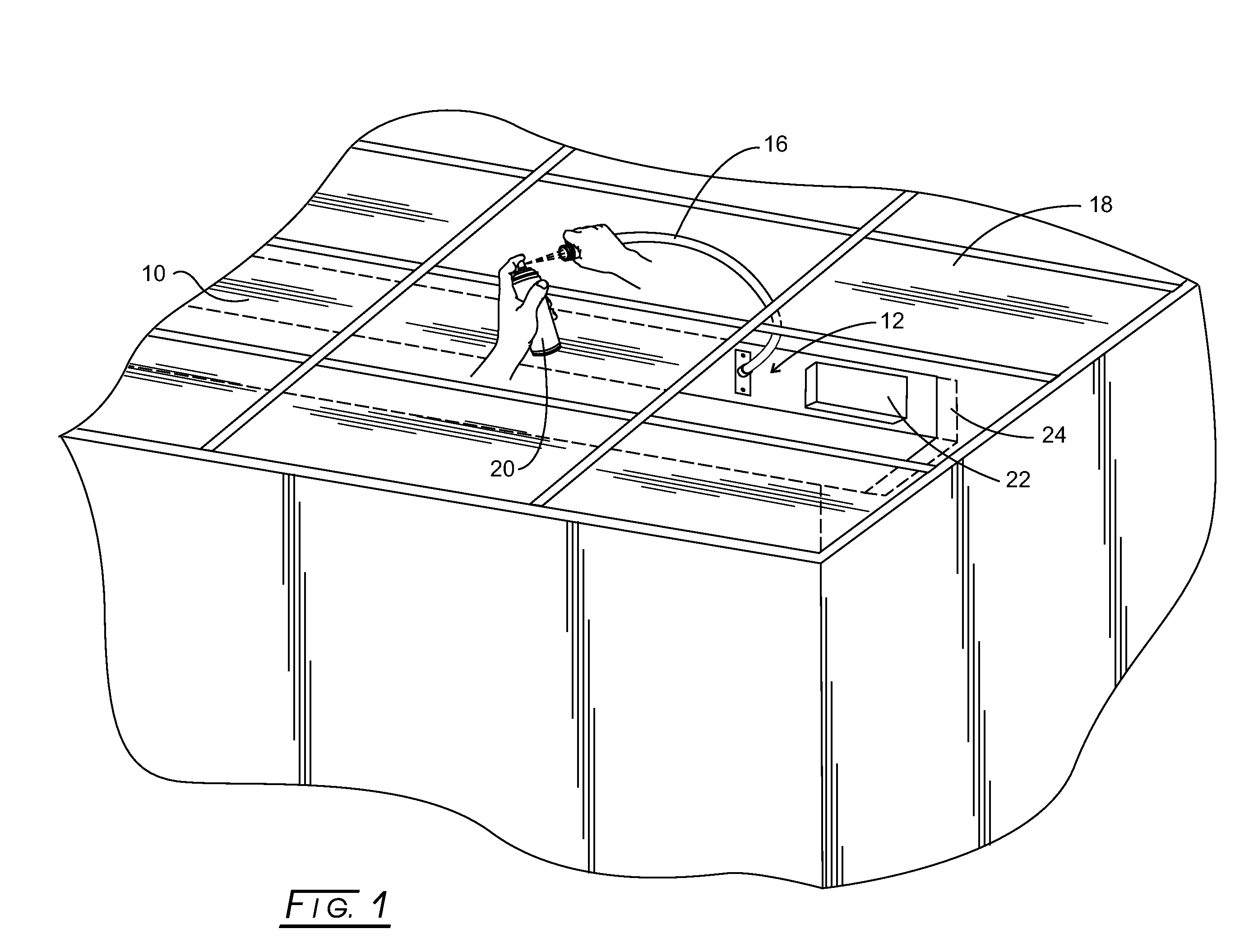
[0024]As illustrated in FIG. 1, a section of HVAC ductwork or duct, 10, has a ductwork mounting plate assembly, 12, affixed to duct 10 by screws and covering an aperture formed in duct 10. Each ductwork mounting plate assembly retains one end of a flexible, plenum rated, flexible hose, 16. For present purposes, “plenum rated” means that the hose meets all of the specifications and safety (e.g., fire) requirements that the ductwork meets according to applicable fire and other building codes and regulations. The other end of the hose terminates at the level of a ceiling, 18, below which ductwork 10 runs.

[0025]In this embodiment, flexible hose 16 just lies atop ceiling 18. Alternatively, hose 16 can be held by a clip attachment, which is part of a ceiling access plate assembly, as illustrated later herein. By removing a ceiling tile from ceiling 18, a can of smoke, 20, can be sprayed into an open end of hose 16 for introducing smoke into duct 10. Such smoke travels to a duct-mounted sm...


PUM


Abstract

An assembly for testing of smoke detectors, installed to detect the presence of smoke in ductwork or through a smoke protected opening, and includes a plenum rated hose assembly having a duct end and a smoke end. The hose assembly smoke end is extendable to within the duct and is terminated with a nozzle directable at an inlet tube of a smoke detector associated with the duct, or to the detector protecting a smoke protected opening. A duct mounting plate is adapted to be sealingly installed to cover an aperture formed within the duct and to retain the hose assembly duct end. Smoke is directed into the hose smoke end. The smoke exits the hose through the nozzle and towards the inlet tube of the duct-mounted smoke detector, or towards the detector for a smoke protected opening, for testing of the smoke detector.

Description

CROSS-REFERENCE TO RELATED APPLICATIONS[0001]This application claims benefit of provisional application Ser. No. 61 / 254,817, filed on Oct. 26, 2009.STATEMENT REGARDING FEDERALLY SPONSORED RESEARCH[0002]Not applicable.BACKGROUND[0003]The present disclosure relates to HVAC (heating ventilating air conditioning) installed duct smoke detectors and more particularly to their testing. Duct mounted smoke detectors are installed in particular locations to meet certain requirements of, for example, the Ohio Building Code, as embodied in the Ohio Mechanical Code or OMC:1. Mounted on the return air handler ductwork for all air handlers which, individually or as part of a system, have a design capacity greater than 2000 cfm. Installed upstream of any filters, exhaust air connections, outdoor connections, or decontamination equipment and appliances. (OMC606.2.1);2. Where return air risers serve two or more stories and serve any portion of a return air system having a design capacity greater than...

Claims


Application Information

Patent Timeline
Patent Type & Authority Applications(United States)
IPC IPC(8): G01M3/02
CPCG08B29/145G08B17/113
Inventor TOWNSEND, ROBERT L.BOLANDER, PAUL
Owner TOWNSEND ROBERT L
Why Eureka
Try Eureka