Control Strategy for an Engine

a technology of control strategy and engine, which is applied in the direction of electric control, combustion engines, machines/engines, etc., can solve problems such as reducing engine efficiency, and achieve the effect of increasing engine operating efficiency and optimum operating rang

Inactive Publication Date: 2011-04-28
EATON INTELLIGENT POWER LTD
View PDF26 Cites 32 Cited by
  • Summary
  • Abstract
  • Description
  • Claims
  • Application Information

AI Technical Summary

Benefits of technology

[0004]A method of controlling an engine is disclosed. The engine includes a combustion air boosting system for supplying a flow of pressurized combustion air to the engine. The boosting system includes a supercharger and a turbocharger. The supercharger is mechanically coupled to the engine. The turbocharger is disposed downstream from the supercharger. The boosting system further includes a combustion air bypass duct for bypassing a flow of air around the supercharger, and a combustion air bypass valve for controlling the flow of air through the combustion air bypass duct. The method includes maintaining operation of the turbocharger within an optimum operating range; manipulating the combustion air bypass valve to create a negative pressure differential across the supercharger between an inlet of the supercharger and an outlet of the supercharger to generate a rotational output of the supercharger; and transmitting the rotational output of the supercharger to the engine to increase an operating efficiency of the engine.
[0005]In another aspect of the invention, a method of controlling an engine is disclosed. The engine includes a combustion air boosting system for supplying a flow of pressurized combustion air to the engine. The boosting system includes a supercharger and a turbocharger. The supercharger is mechanically coupled to the engine. The turbocharger is disposed downstream from the supercharger. The boosting system further includes a combustion air bypass duct for bypassing a flow of air around the supercharger, and a combustion air bypass valve for controlling the flow of air through the combustion air bypass duct. The combustion air bypass valve includes an open position permitting unobstructed airflow through the combustion air bypass duct and a closed position preventing airflow through the combustion air bypass duct. The method includes maintaining operation of the turbocharger within an optimum operating range; manipulating the combustion air bypass valve to an intermediate position between the open position and the closed position to create a negative pressure differential across the supercharger between an inlet of the supercharger and an outlet of the supercharger to generate a torque; and transmitting the torque to the engine to increase an operating efficiency of the engine.
[0006]Accordingly, the method increases the operating efficiency of the engine by using the supercharger to convert excess combustion air pressure supplied by the turbocharger into torque, which is transmitted from the supercharger back to the engine. Additionally, the supercharger may be used on demand to provide the flow of combustion air to the engine during acceleration, before the turbocharger reaches an optimum operating efficiency, thereby providing near instantaneous pressurized combustion air on demand.

Problems solved by technology

However, the mechanical linkage between the supercharger and the engine draws power from the engine to operate the supercharger, thereby reducing the efficiency of the engine.

Method used


Image

  • Control Strategy for an Engine
  • Control Strategy for an Engine
  • Control Strategy for an Engine

Examples


Embodiment Construction

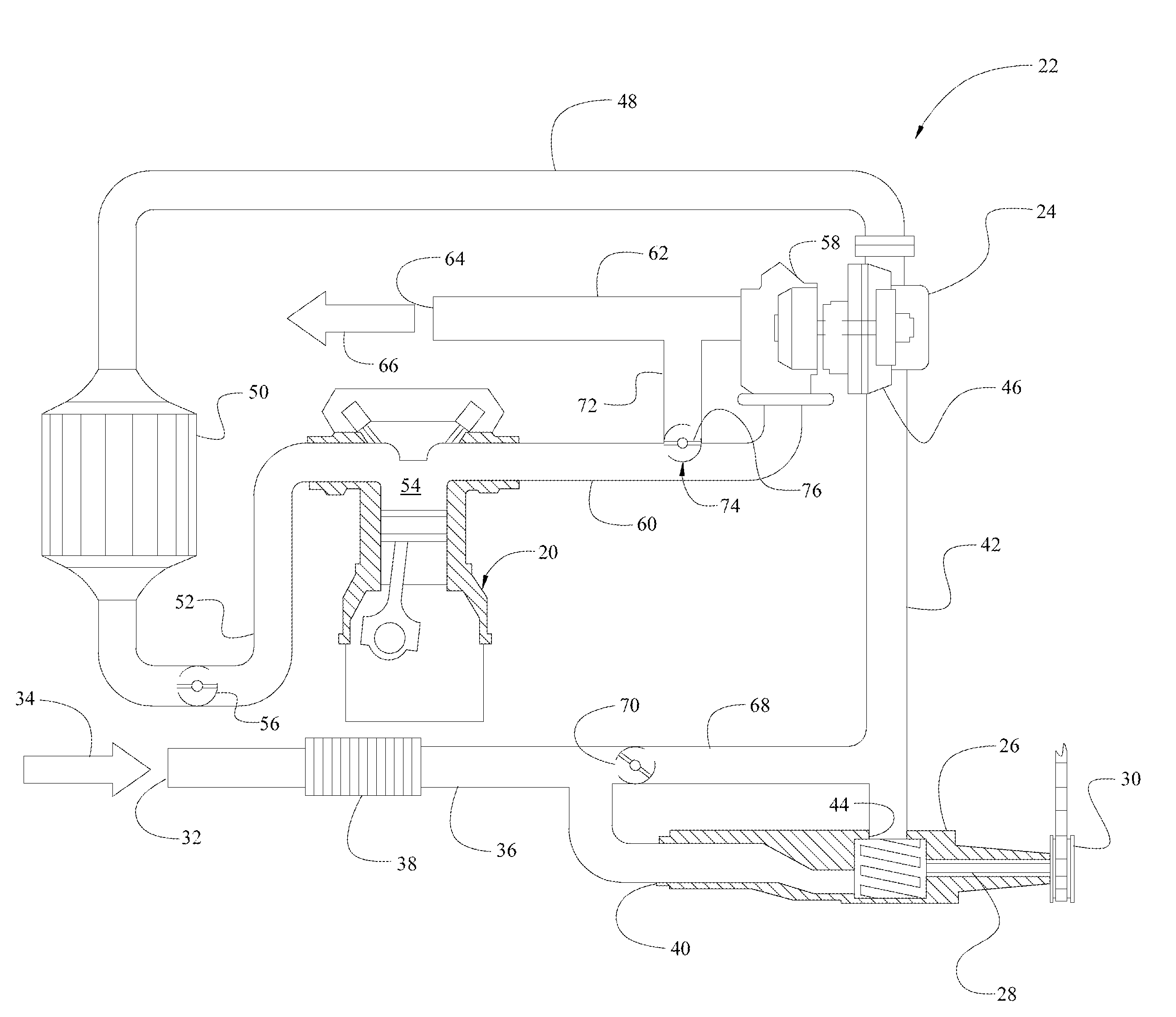
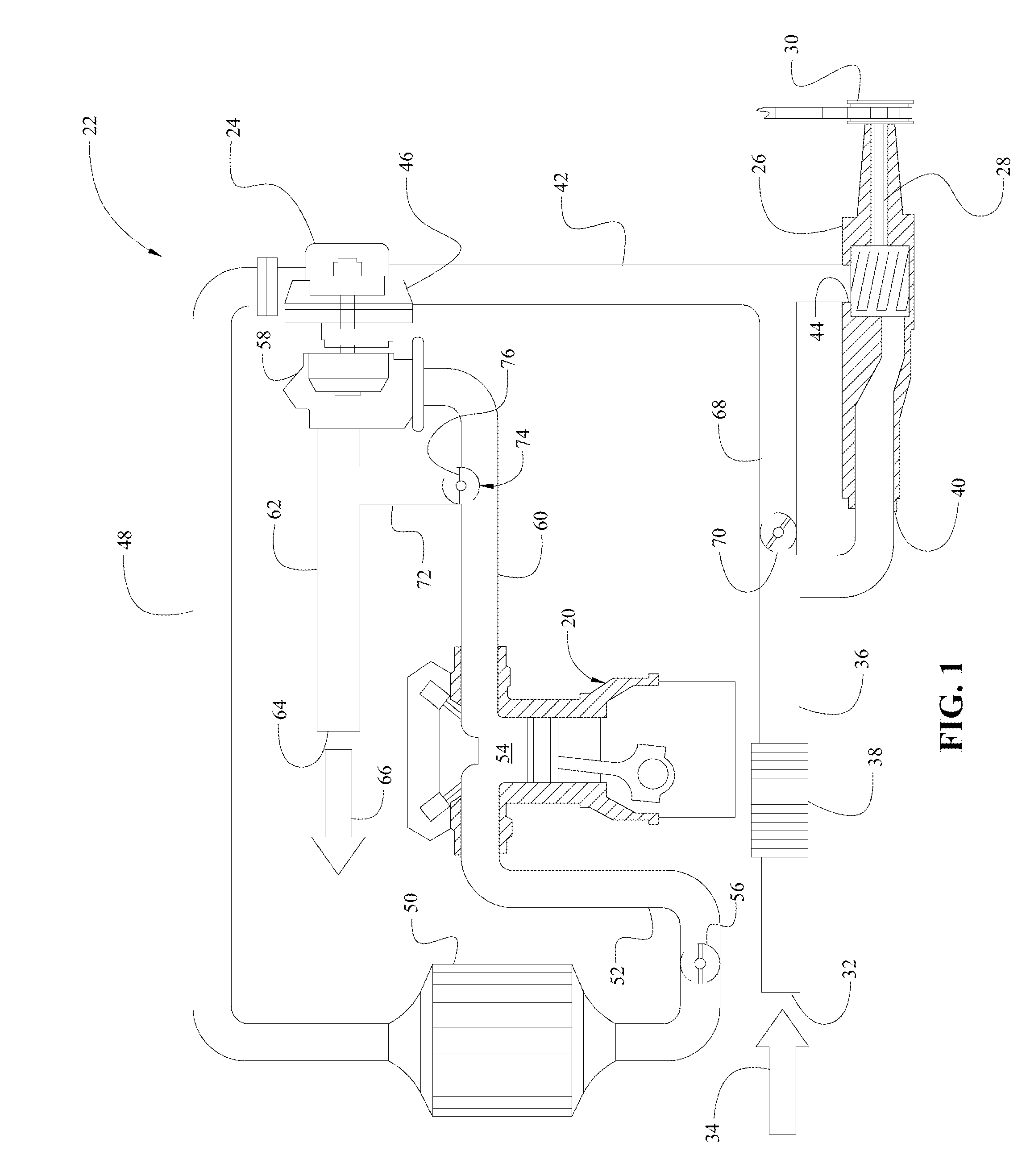
[0010]Referring to the Figures, wherein like numerals indicate corresponding parts throughout the several views, an internal combustion engine is shown generally at 20 in FIG. 1. The engine 20 includes a conventional engine, such as a diesel engine or a gasoline engine. As shown in FIG. 1, the engine 20 includes a “superturbo” boosting system 22, which includes both a turbocharger 24 and a supercharger 26 disposed sequentially in-line with each other to increase the boost, i.e., pressure, of combustion air of the engine 20.

[0011]The turbocharger 24 is powered by exhaust gas provided by the engine 20 as is well known. The supercharger 26 is mechanically linked to the engine 20, and is directly powered by the engine 20. The supercharger 26 includes a drive shaft 28 and a clutch 30 interconnecting the engine 20 and the drive shaft 28 of the supercharger 26. The clutch 30 is configured for selectively engaging and disengaging the supercharger 26. It should be understood by those skilled...


PUM


Abstract

A method of controlling an engine includes manipulating a wastegate to maintain the operation of the turbocharger within an optimum operating range. A combustion air bypass valve is manipulated between an open position and a closed position to create a negative pressure differential across a supercharger. The supercharger is sequentially disposed in-line before the turbocharger. The negative pressure differential is converted into a torque by the supercharger and transmitted from the supercharger back to the engine to increase the operating efficiency of the engine.

Description

TECHNICAL FIELD[0001]The invention generally relates to a method of controlling an engine, and more specifically to a method of controlling an engine including a combustion air boosting system having a supercharger and a turbocharger disposed in-line relative to each other.BACKGROUND OF THE INVENTION[0002]Internal combustion engines, particularly diesel engines, often include a boosting system to increase the pressure of the combustion air. The boosting system may include a turbocharger, which includes a compressor actuated by a turbine that is powered by a flow of exhaust gas from the engine. As is well known, the turbocharger lags behind the operation of the engine until the flow of exhaust gas through the turbine is sufficient to operate the compressor to pressurize the combustion air. Alternatively, the boosting system may include a supercharger, which is mechanically coupled to the engine, typically through a clutch. Because the supercharger is mechanically coupled to the engin...

Claims


Application Information

Patent Timeline
Patent Type & Authority Applications(United States)
IPC IPC(8): F02B33/00F02D23/00
CPCF02B33/34F02B37/04F02B37/12Y02T10/144F02D2009/0279F02D2009/0283F02D41/0007Y02T10/12F02D41/00
Inventor SUHOCKI, CHRISTOPHERSITAR, MICHAEL J.
Owner EATON INTELLIGENT POWER LTD
Why Eureka
Try Eureka