Thermoelectric generator

Active Publication Date: 2011-04-28
STMICROELECTRONICS CROLLES 2
View PDF10 Cites 14 Cited by
  • Summary
  • Abstract
  • Description
  • Claims
  • Application Information

AI Technical Summary

Benefits of technology

[0009]An object of an embodiment of the present invention is to provide such a generator which is easy to manufacture.
[0010]An obj

Problems solved by technology

A disadvantage of such a solution is that it cannot be used in the case of fixed equipment, for example, a television set or a computer.
However, such devices have a very low efficiency.
In practice, t

Method used


Image

  • Thermoelectric generator
  • Thermoelectric generator

Examples


Example

[0023]For clarity, the same elements have been designated with the same reference numerals in the different drawings and, further, the various drawings are not to scale.

[0024]An aspect of an embodiment of the present invention is to provide a device capable of:

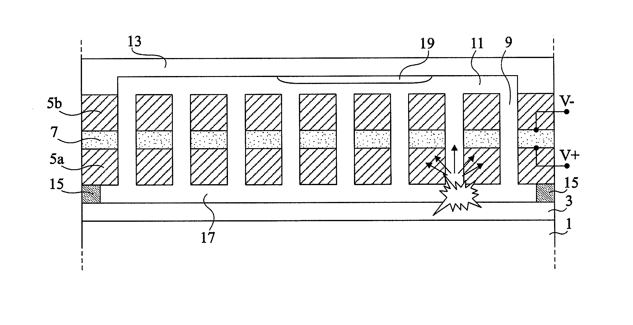
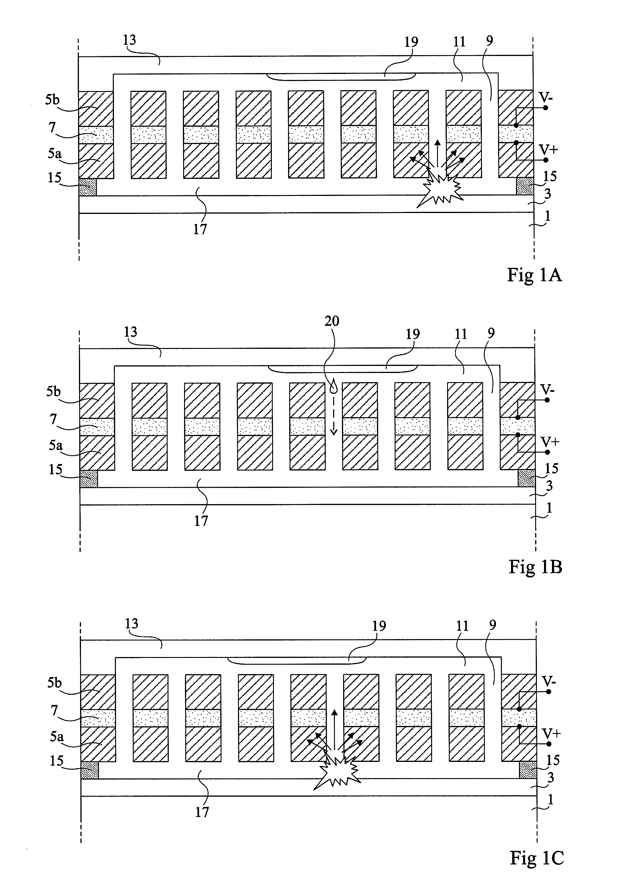
[0025]converting thermal power into mechanical power by means of a liquid abruptly evaporating when it comes in contact with a hot surface, thus creating a local overpressure; and

[0026]converting this overpressure into electric power by means of a piezoelectric element.

[0027]FIGS. 1A to 10 are simplified cross-section views illustrating an embodiment of a thermoelectric generator and its operating principle.

[0028]In this example, the thermoelectric generator is formed at the surface of an integrated circuit chip formed inside and on top of a semiconductor substrate 1 and comprising, at the surface of the substrate, a stack 3 of conductive interconnect layers and of insulating layers. In operation, the integrated circuit chip g...


PUM


Abstract

A thermoelectric generator including, between first and second walls delimiting a tightly closed space, a layer of a piezoelectric material connected to output terminals; a plurality of openings crossing the piezoelectric layer and emerging into first and second cavities close to the first and second walls; and in the tight space, drops of a liquid, the first wall being capable of being in contact with a hot source having a temperature greater than the evaporation temperature of the liquid and the second wall being capable of being in contact with a cold source having a temperature smaller than the evaporation temperature of the liquid.

Description

CROSS REFERENCE TO RELATED APPLICATIONS[0001]This application claims the priority benefit of French patent application Ser. No. 09 / 57493, filed on Oct. 26, 2009, entitled “THERMOELECTRIC GENERATOR,” which is hereby incorporated by reference to the maximum extent allowable by law.BACKGROUND OF THE INVENTION[0002]1. Field of the Invention[0003]The present invention relates to a thermoelectric generator, that is, a device capable of generating electricity from a heat source. It especially aims at the exploitation of the thermal power generated by certain types of equipment, for example, a hot surface of an integrated circuit chip, a car muffler, the roof of a house, or any other hot surface.[0004]2. Discussion of the Related Art[0005]In certain mobile devices, for example, telephones, watches, or pacemakers, the use of piezoelectric microgenerators has been provided to generate electricity from the mechanical vibrations resulting from the user's movements. This enables to at least part...

Claims


Application Information

Patent Timeline
IPC IPC(8): H02N2/18
CPCH02N2/18
Inventor SKOTNICKI, THOMAS
Owner STMICROELECTRONICS CROLLES 2
Why Eureka
Try Eureka