Interactive input system incorporating multi-angle reflecting structure

a multi-angle reflecting and input system technology, applied in the field of interactive input systems, can solve the problems of retroreflecting units, high manufacturing cost, and significant cost to the overall touch system

Inactive Publication Date: 2011-04-28
SMART TECH INC (CA)
View PDF102 Cites 12 Cited by
  • Summary
  • Abstract
  • Description
  • Claims
  • Application Information

AI Technical Summary

Benefits of technology

[0009]In one embodiment, the multi-angle reflecting structure comprises at least one series of reflective elements extending along the bezel. The reflective elements are configured to reflect emitted radiation from the at least one radiation source towards the at least one imaging device. Each reflective element is of a size smaller than the pixel resolution of the at least one imaging device and presents a reflective surface that is angled to reflect emitted radiation from the at least one radiation source towards the at least one imaging device. The reflecting surface may be generally planar, generally convex, or generally concave. The configuration of the reflective surfaces may also vary over the length of the bezel.
[0010]In one embodiment, the at least one radiation source is positioned adjacent the at least one imaging device and emits non-visible radiation such as for example infrared radiation. In this case, the at least one radiation source comprises one or more infrared light emitting diodes.

Problems solved by technology

Although this illuminated bezel is effective, it is expensive to manufacture and can add significant cost to the overall touch system.
Although the use of the retroreflecting unit to reflect and direct light into the coordinate input region is less costly than employing illuminated bezels, problems with such a retroreflecting unit exist.
However, when the angle of incident light on the retroreflecting surface becomes larger, the performance of the retroreflecting unit degrades resulting in uneven illumination of the coordinate input region.
As a result, the possibility of false pointer contacts and / or missed pointer contacts is increased.

Method used


Image

  • Interactive input system incorporating multi-angle reflecting structure
  • Interactive input system incorporating multi-angle reflecting structure
  • Interactive input system incorporating multi-angle reflecting structure

Examples


Embodiment Construction

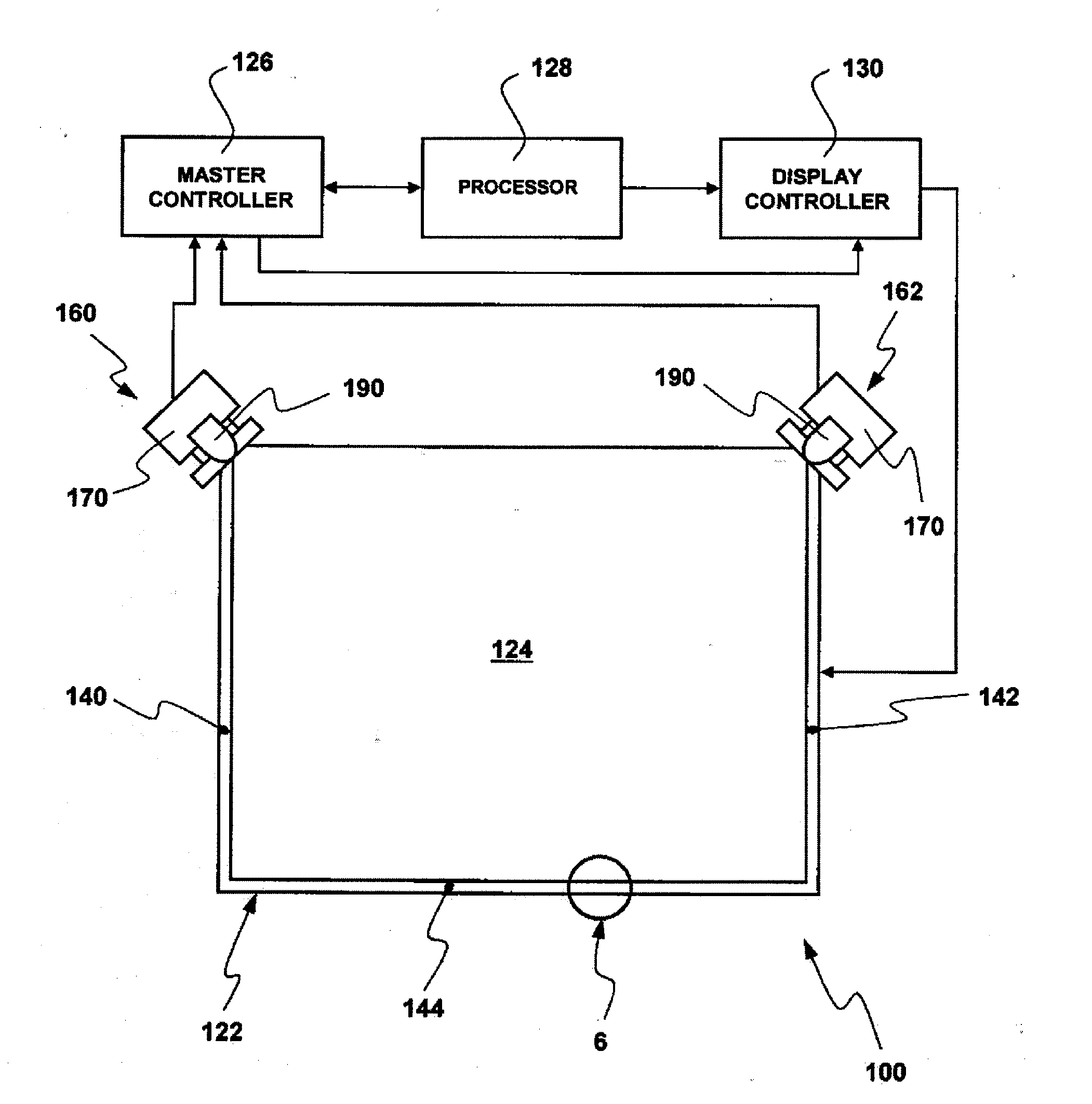
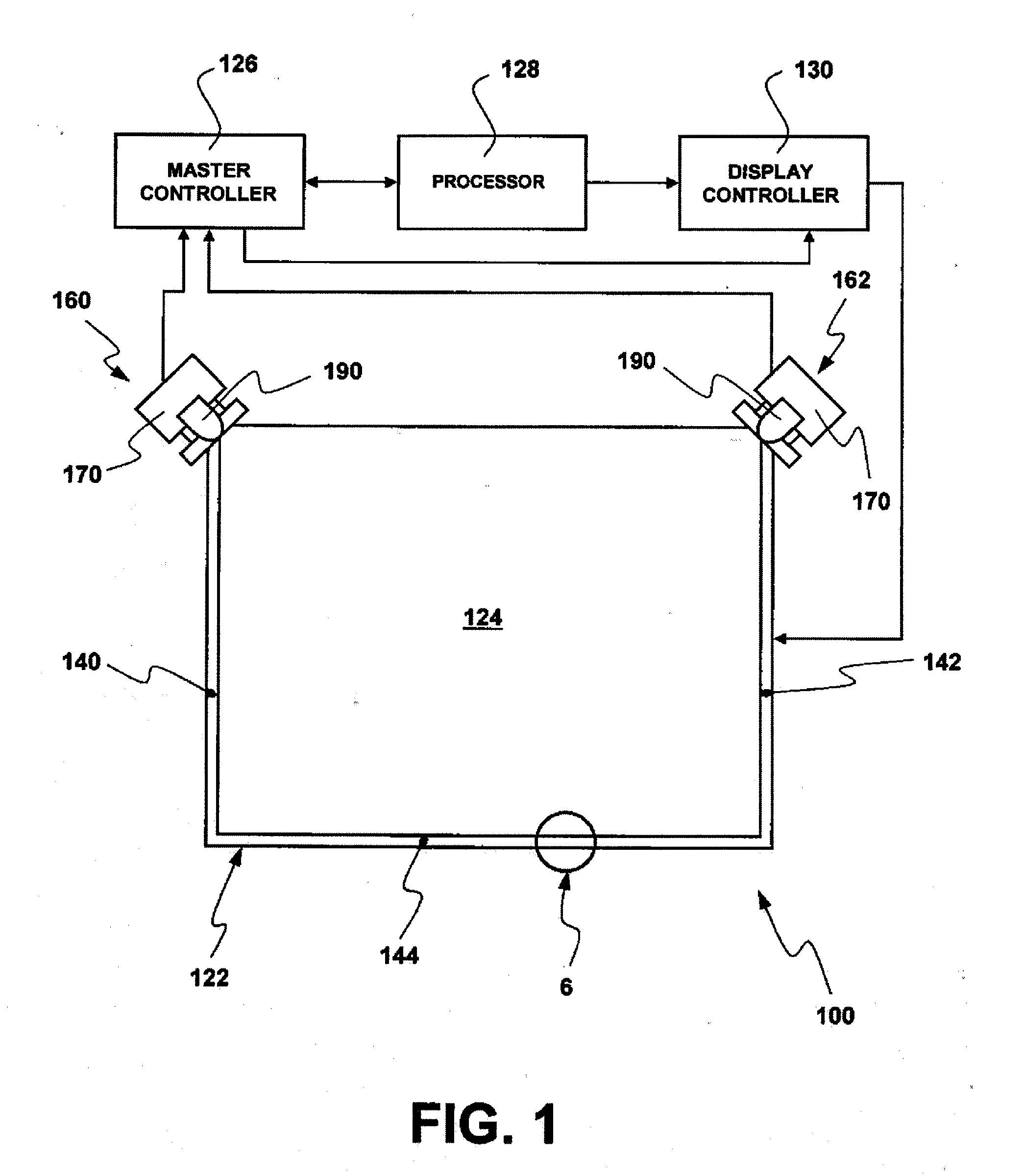
[0035]Turning now to FIG. 1, an interactive input system that allows a user to inject input such as digital ink, mouse events etc. into an application program is shown and is generally identified by reference numeral 100. In this embodiment, interactive input system 100 comprises an assembly 122 that engages a display unit (not shown) such as for example, a plasma television, a liquid crystal display (LCD) device, a flat panel display device, a cathode ray tube display or monitor etc. and surrounds the display surface 124 of the display unit. The assembly 122 employs machine vision to detect pointers brought into proximity with the display surface 124 and communicates with a master controller 126. The master controller 126 in turn communicates with a general purpose computing device 128 executing one or more application programs. General purpose computing device 128 processes the output of the assembly 122 and provides display output to a display controller 130. Display controller 1...


PUM


Abstract

An interactive input system comprises at least one imaging device having a field of view looking into a region of interest. At least one radiation source emits radiation into the region of interest. A bezel at least partially surrounds the region of interest. The bezel comprises a multi-angle reflecting structure to reflect emitted radiation from the at least one radiation source towards the at least one imaging device.

Description

FIELD OF THE INVENTION[0001]The present invention relates generally to interactive input systems and in particular, to an interactive input system incorporating multi-angle reflecting structure.BACKGROUND OF THE INVENTION[0002]Interactive input systems that allow users to inject input (eg. digital ink, mouse events etc.) into an application program using an active pointer (eg. a pointer that emits light, sound or other signal), a passive pointer (eg. a finger, cylinder or other suitable object) or other suitable input device such as for example, a mouse or trackball, are known. These interactive input systems include but are not limited to: touch systems comprising touch panels employing analog resistive or machine vision technology to register pointer input such as those disclosed in U.S. Pat. Nos. 5,448,263; 6,141,000; 6,337,681; 6,747,636; 6,803,906; 7,232,986; 7,236,162; and 7,274,356 assigned to SMART Technologies ULC of Calgary, Alberta, Canada, assignee of the subject applica...

Claims


Application Information

Patent Timeline
Patent Type & Authority Applications(United States)
IPC IPC(8): G06F3/033
CPCG06F3/0428
Inventor UNG, CHARLES
Owner SMART TECH INC (CA)
Why Eureka
Try Eureka