Light source unit and projector

Active Publication Date: 2011-04-28
CASIO COMPUTER CO LTD
View PDF4 Cites 27 Cited by
  • Summary
  • Abstract
  • Description
  • Claims
  • Application Information

AI Technical Summary

Benefits of technology

[0024]Since it is possible to effect a duty drive in which the excitation light source of the excitation light shining device and the semiconductor light emitting devices of the two types of light sources are switched on and off, there can be provided the light source unit w

Problems solved by technology

However, when a white discharge lamp is used as a light source, the color of light from the light source is divided by a color wheel including red, green and blue color filters to cut off other light than light to be used, leading to a problem that the utilization efficiency of light from the light source is low.
However, since excitation light needs to be shone individually onto the luminescent light emitting areas of the respective colors formed on a surface of the luminescent wheel, there is caused a problem that a large load has to be borne by the excitation light source which is driven at all times. Because of this, the drive output of the excitation light source needs to be suppressed to as to suppress the increase in temperature thereof.
Thus, in the event that a period of time when the light ray of the specific wavelength band is attempted to be lengthened, there is no other way but to adjust it by shortening the periods of time when the light rays of the other wavelength bands are emitted, leading to a problem that the utilization efficiency of light i

Method used


Image

  • Light source unit and projector
  • Light source unit and projector
  • Light source unit and projector

Examples


Embodiment Construction

[0034]Hereinafter, a preferred mode for carrying out the invention will be described by use of the accompanying drawings. Although various limitations which are technically preferable for carrying out the invention are imposed on an embodiment which will be described below, the scope of the invention is not limited in any way to the following description and illustrated examples.

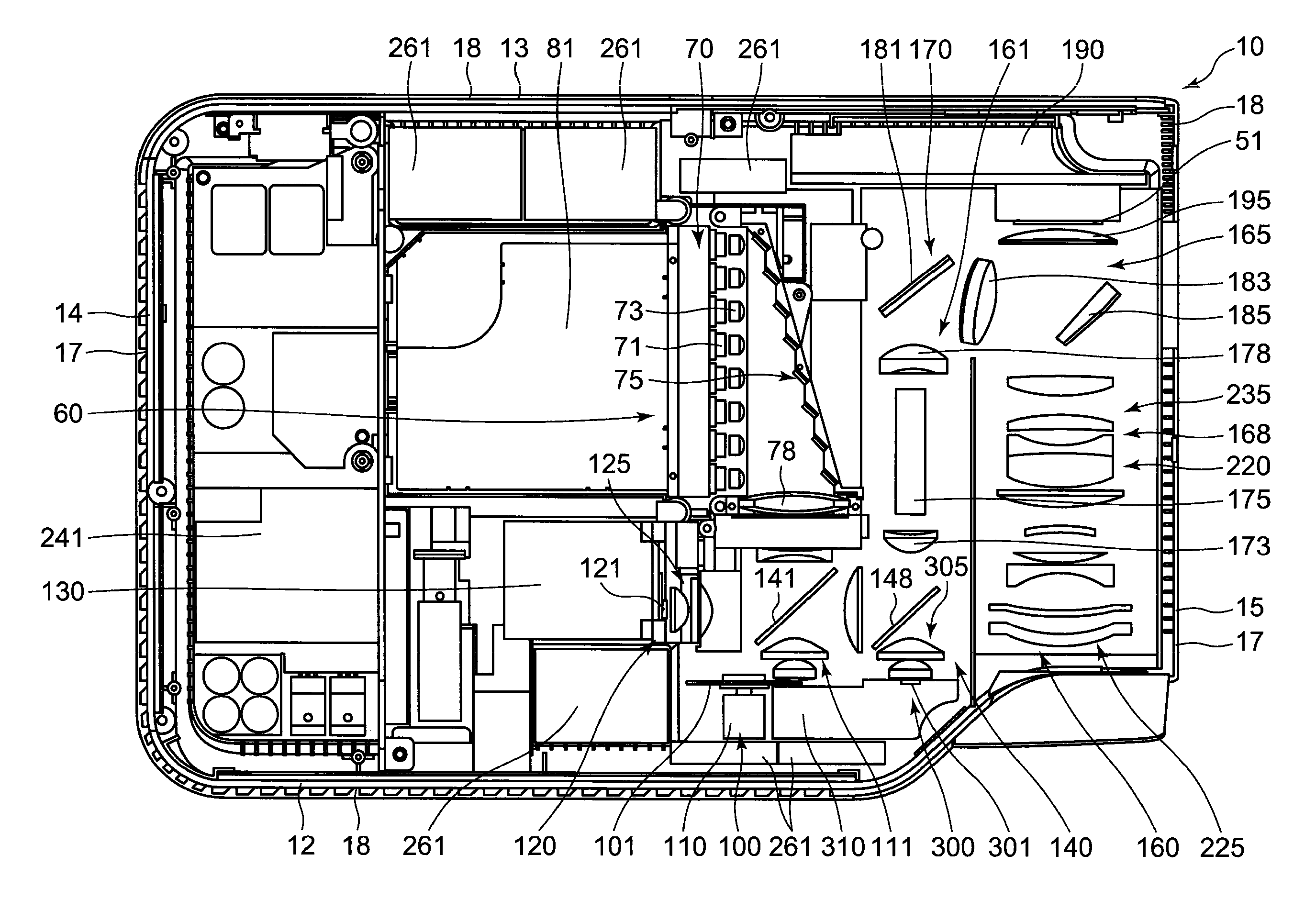
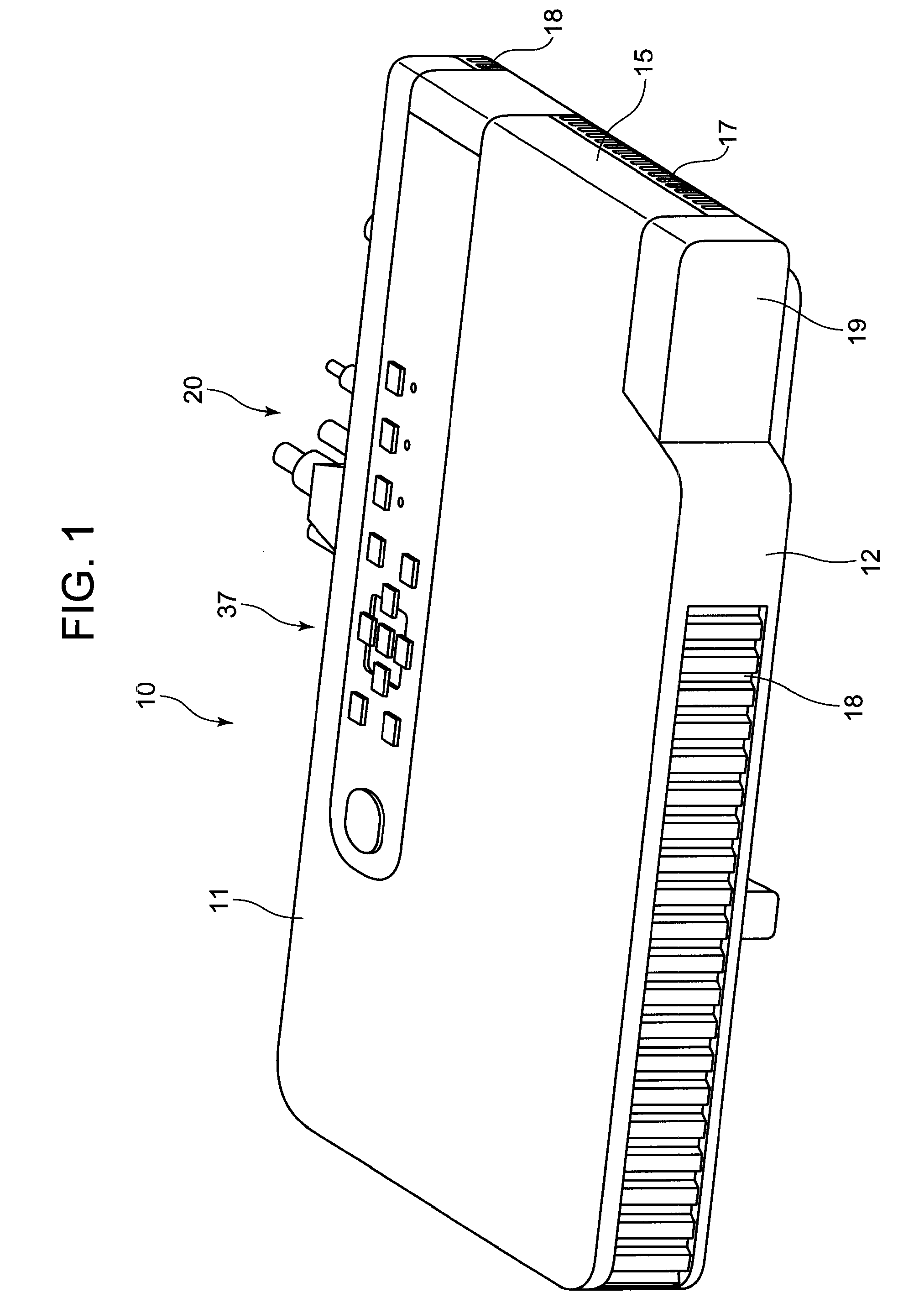
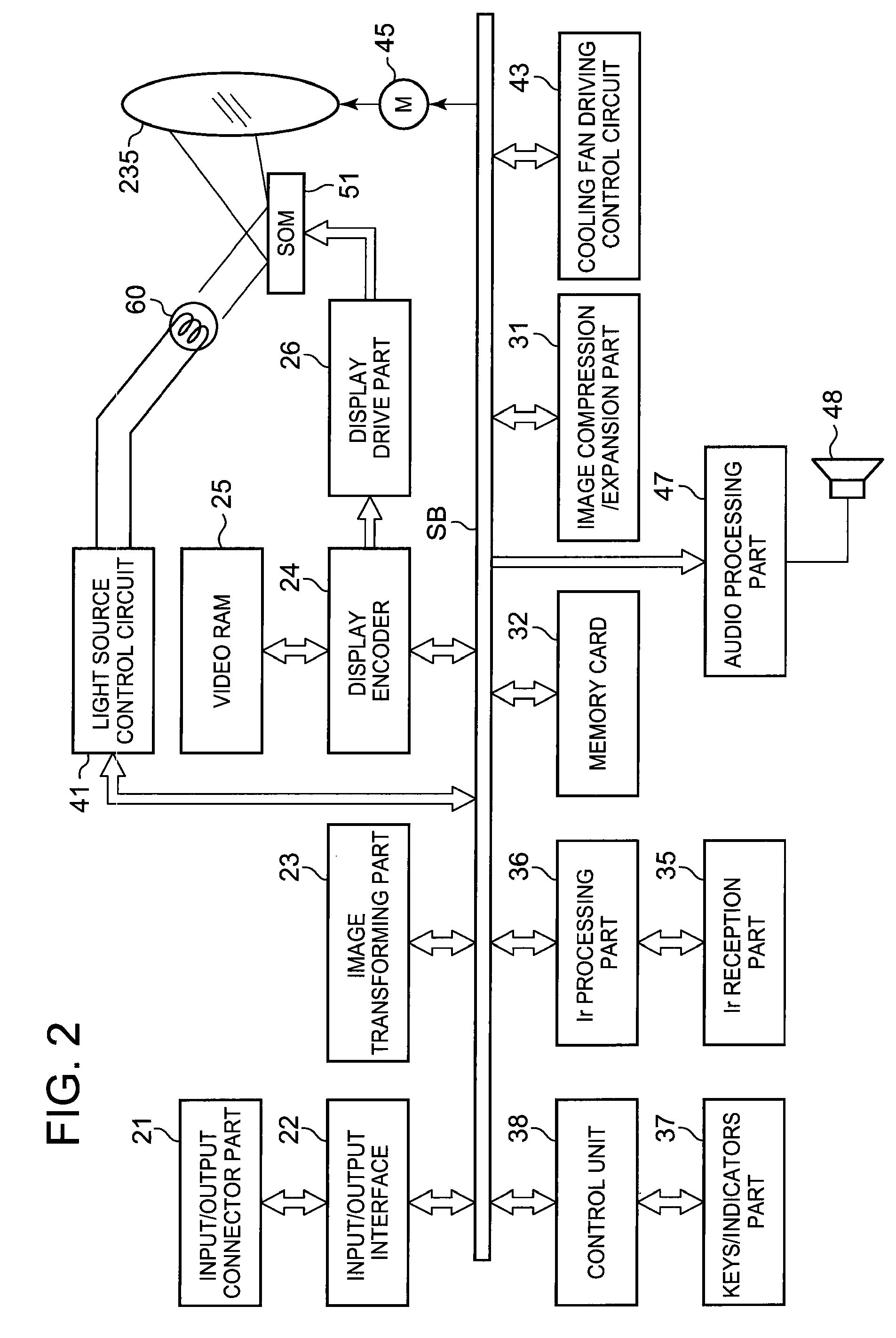
[0035]Hereinafter, a mode for carrying out the embodiment will be described. A projector 10 includes a light source unit 60, a display device 51, a light guiding optical system 170 for guiding light from the light source unit 60 to the display device 51, a projection-side optical system 220 for projecting an image emitted from the display device 51 onto a screen, and a projector control device for controlling the light source unit 60 and the display device 51.

[0036]The light source unit 60 further includes an excitation light shining device 70, a luminescent light emitting device 100 having a luminescent whe...


PUM


Abstract

To provide a light source unit which prevents a reduction of light emitting efficiency in a luminescent material layer and a projector, a projector includes a light source unit, a display device and a projector control device, the light source unit includes an excitation light shining device, a luminescent wheel on which a luminescent material layer is laid circumferentially which receives the excitation light to emit luminescent light of a predetermined wavelength band, two types of light source devices for emitting light rays of wavelength bands which are different from the predetermined wavelength band, and a light source control device for controlling individually the emission of light by the excitation light shining device and the two types of light source devices and for controlling the rotating speed of the luminescent wheel in accordance with a period of time when the excitation light shining device is turned on.

Description

CROSS-REFERENCE TO RELATED APPLICATIONS[0001]This application is based upon and claims the benefit of priority under 35 USC 119 of Japanese Patent Application No. 2009-247708 filed on Oct. 28, 2009, the entire disclosure of which, including the description, claims, drawings and abstract thereof, is incorporated herein by reference.BACKGROUND OF THE INVENTION[0002]1. Field of the Invention[0003]The present invention relates to a light source unit and a projector which includes the light source unit.[0004]2. Description of the Related Art[0005]In these days, data projectors are used on many occasions as image projection apparatuses which project images including images of screens and video images of personal computers, as well as images based on image data which is stored in memory cards on to a screen. These projectors are such that light emitted from a light source is collected to a micromirror device called DMD (Digital Micromirror Device) or a liquid crystal plate for display of a...

Claims


Application Information

Patent Timeline
IPC IPC(8): G03B21/20F21V9/16
CPCG03B21/2013G03B21/204G03B21/206G03B33/08G03B21/2053
Inventor SHIBASAKI, MAMORU
Owner CASIO COMPUTER CO LTD
Why Eureka
Try Eureka