Synchronized Express and Local Trains for Urban Commuter Rail Systems

a technology of urban commuter rail and express trains, applied in the direction of distance measurement, instruments, ways, etc., can solve the problems of underutilization of the subway system, inability to recover huge infrastructure costs, and inhibiting the construction of additional capacity, so as to reduce the travel time of all passengers and optimize the utilization of subway system resources.

Active Publication Date: 2011-04-28
INTEGRATED TRANSPORTATION TECH
View PDF26 Cites 44 Cited by
  • Summary
  • Abstract
  • Description
  • Claims
  • Application Information

AI Technical Summary

Benefits of technology

[0016]It is therefore an object of this invention to provide a system and method of operating a subway train system that optimizes the utilization of subway system resources including the subway tracks, subway stations, and subway trains, while substantially reducing passenger travel time for all passengers.
[0017]It is a further object of this invention to reduce passenger total travel time at minimal system cost, resulting in reduced overcrowding of subway trains by improving the passenger throughput rate of the system.

Problems solved by technology

Underutilization of the subway system is a financial disaster, in that the huge infrastructure costs are not recouped; as such, subway commuter rail construction is often confined to routes that are capable of providing adequate ridership.
But these infrastructure costs also inhibit additional capacity from being constructed, if demand for the subway system exceeds its capacity.
As a result, many of the world's urban subway systems are overcrowded; indeed, the overcrowded subway systems in Seoul, Korea and Tokyo, Japan often receive worldwide publicity.
The constraint of high infrastructure construction costs is also reflected in passenger travel times. Commuter rail systems present the particular problem that passengers are free to board and exit the subway train at any station along the line.
The subway system designer and operator is thus faced with a tradeoff between the number of stations along a line and the passenger travel time from origin to terminus.
Specifically, while a larger number of stations along a line improves the proximity of the subway to a wide range of destinations, this larger number of stations will necessarily slow the passenger travel time of passengers that do not want to exit the train at a particular station.
As evident from this description, however, those subway systems or portions of subway systems that are limited to only a single track in each direction of travel have not been able to provide express service.
In such systems, the ultimate speed of travel of an express train, which as such does not stop at local stations located between express stations, will eventually necessarily be limited by the speed of any local train that the express train catches up to along the route.
Side track facilities are typically more prevalent at surface rail stations than at subway stations, because the excavation cost etc. involved in adding a side track at a subway station is typically prohibitive.
If an existing two-track system wished to add express service, the cost of adding side tracks 4WE, 4EW in the manner shown in FIG. 1a is especially prohibitive, and for that reason is seldom carried out.
And even in those surface or subway systems in which side tracks are provided at stations, significant wait time is often required for passengers to change from one train to another, as mentioned above.
However, each of these conventional train scheduling methods and systems apply to the scheduling of trains that are not concerned with allowing passengers to board or de-board at intermediate stations along the route.
In other words, these conventional scheduling methods and systems do not solve many of the important and dominant issues involved in commuter rail systems, particularly subway systems.

Method used


Image

  • Synchronized Express and Local Trains for Urban Commuter Rail Systems
  • Synchronized Express and Local Trains for Urban Commuter Rail Systems
  • Synchronized Express and Local Trains for Urban Commuter Rail Systems

Examples


Embodiment Construction

[0054]This invention will be described in connection with its embodiments, as implemented into an urban commuter rail system in which at least a significant portion of the system is an underground subway system. These embodiments are described in this specification because it is contemplated that this invention will be especially beneficial when utilized in such an application. However, it is contemplated that this invention can also provide similar important benefits if implemented in other applications and environments. Accordingly, it is to be understood that the following description is provided by way of example only, and is not intended to limit the true scope of this invention as claimed.

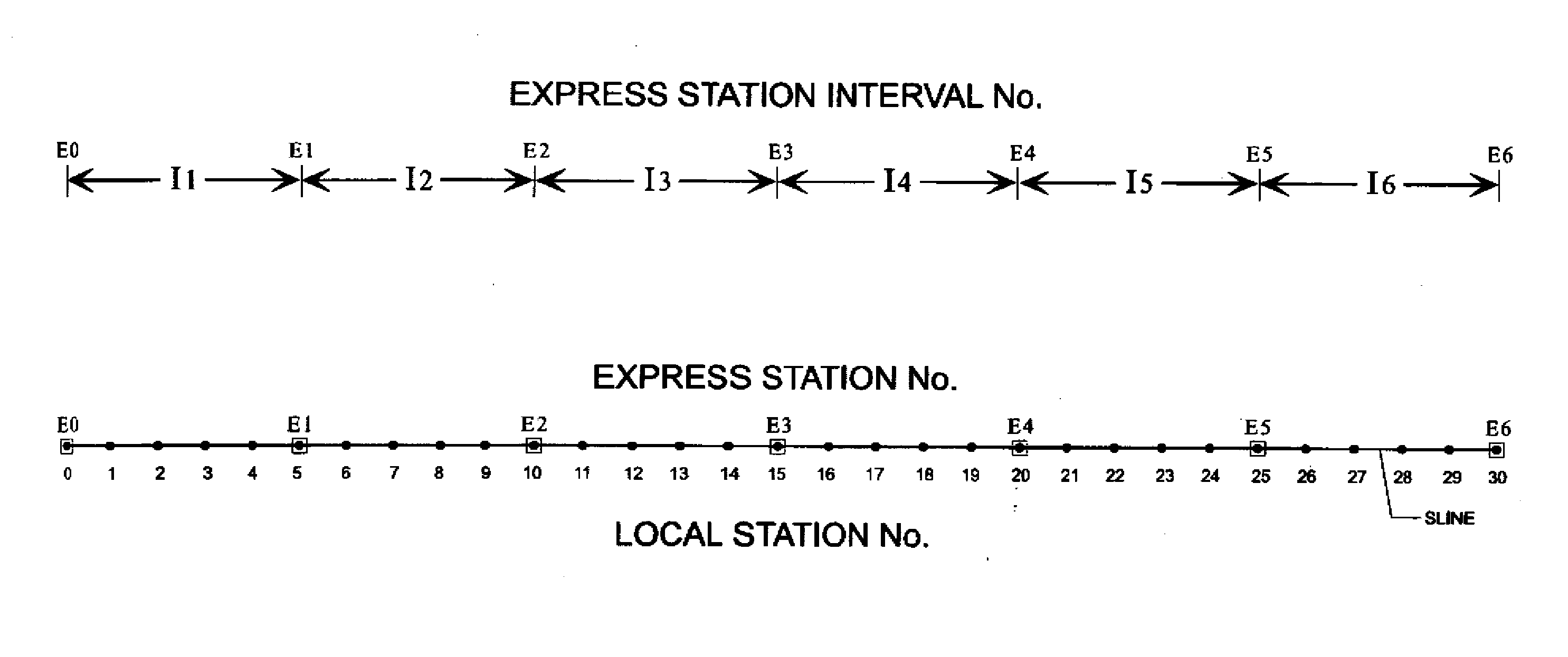
[0055]FIG. 2a schematically illustrates the context of embodiments of this invention in connection with subway line SLINE, which travels from an origin to a terminus. For purposes of this contextual description, subway line SLINE will be discussed in connection with a single direction of trav...


PUM


Abstract

A computerized system and method of managing subway trains along a two-track subway line to allow express travel in combination with local service. Express trains catch up to local trains at express stations along the line, and provision is made to allow the express trains to physically or “virtually” pass the local train at those stations. Embodiments in which the express trains physically pass the local train include direct train-to-train transfer facilitated by side-by-side tracks at the express station occupying reduced footprint. In other embodiments, virtual passing is accomplished by changing the type of service provided by trains at express intervals: a local train “transforms” into an express train and vice versa. Embodiments enable passengers to transfer between trains at express stations so that these “relay” passengers can travel faster than any specific train.

Description

CROSS-REFERENCE TO RELATED APPLICATIONS[0001]Not applicable.STATEMENT REGARDING FEDERALLY SPONSORED RESEARCH OR DEVELOPMENT[0002]Not applicable.BACKGROUND OF THE INVENTION[0003]This invention is in the field of mass transit systems. Embodiments of this invention are more specifically directed to scheduling and operation of mass transit commuter rail systems.[0004]For many years, citizens of major metropolitan areas throughout the world have relied on commuter rail systems, including surface rail and subways, as an important means of transportation. Because at-grade intersections with motor vehicles are avoided by subway trains, subway systems are especially attractive in densely populated cities. Currently, over two hundred cities in the world operate subway commuter rail systems, serving hundreds of millions of passengers each day.[0005]Commuter rail systems in general, and subway systems in particular, are of course constrained to the physical locations of their tracks and station...

Claims


Application Information

Patent Timeline
Patent Type & Authority Applications(United States)
IPC IPC(8): G06G7/76B61B1/00G06F19/00
CPCB61L23/08B61B1/00B61L27/12B61L27/16B61L23/14B61L27/14
Inventor CHUN, JOONG H.
Owner INTEGRATED TRANSPORTATION TECH
Why Eureka
Try Eureka