
Symmetric and interlocked regional traffic light control method

Inactive Publication Date: 2011-04-28
TSAI HUI TE
View PDF1 Cites 11 Cited by
  • Summary
  • Abstract
  • Description
  • Claims
  • Application Information

AI Technical Summary

Benefits of technology

[0008]An objective of the present invention is to provide a symmetric and interlocked regional traffic light control method, which can reduce vehicle travel times, air pollution, noise pollution, and wasted fuel.
[0019]Accordingly, vehicles traveling with the average vehicle speed move along the axial streets through the control region and the next control region. Therefore, when the vehicles in the control region move with the average vehicle speed they can all travel into another control region before the current allowing travel time period ends. In other words, vehicles in the control regions are able to travel through all connected control regions which can reduce vehicle travel times, air pollution, noise pollution, and wasted fuel.
[0031]Therefore, a symmetric and interlocked regional traffic light control method is provided for reducing metropolitan traffic jams to mitigate and / or obviate the aforementioned problems.

Problems solved by technology

Therefore, regardless of the traveling speeds of any vehicle, it will have to stop at a red light, which increases travel times. Moreover, when a large number of vehicles all stop and wait for a red light, serious air and noise pollution problems are consequently generated, and which also causes traffic jams.
Furthermore, in general, a typical car with a full tank of gas can run about 500 km on highways but only 220 km in cities; in other words, about 56% of the fuel is wasted, which is a tremendous waste of energy.

Method used


Image

  • Symmetric and interlocked regional traffic light control method
  • Symmetric and interlocked regional traffic light control method
  • Symmetric and interlocked regional traffic light control method

Examples


first embodiment

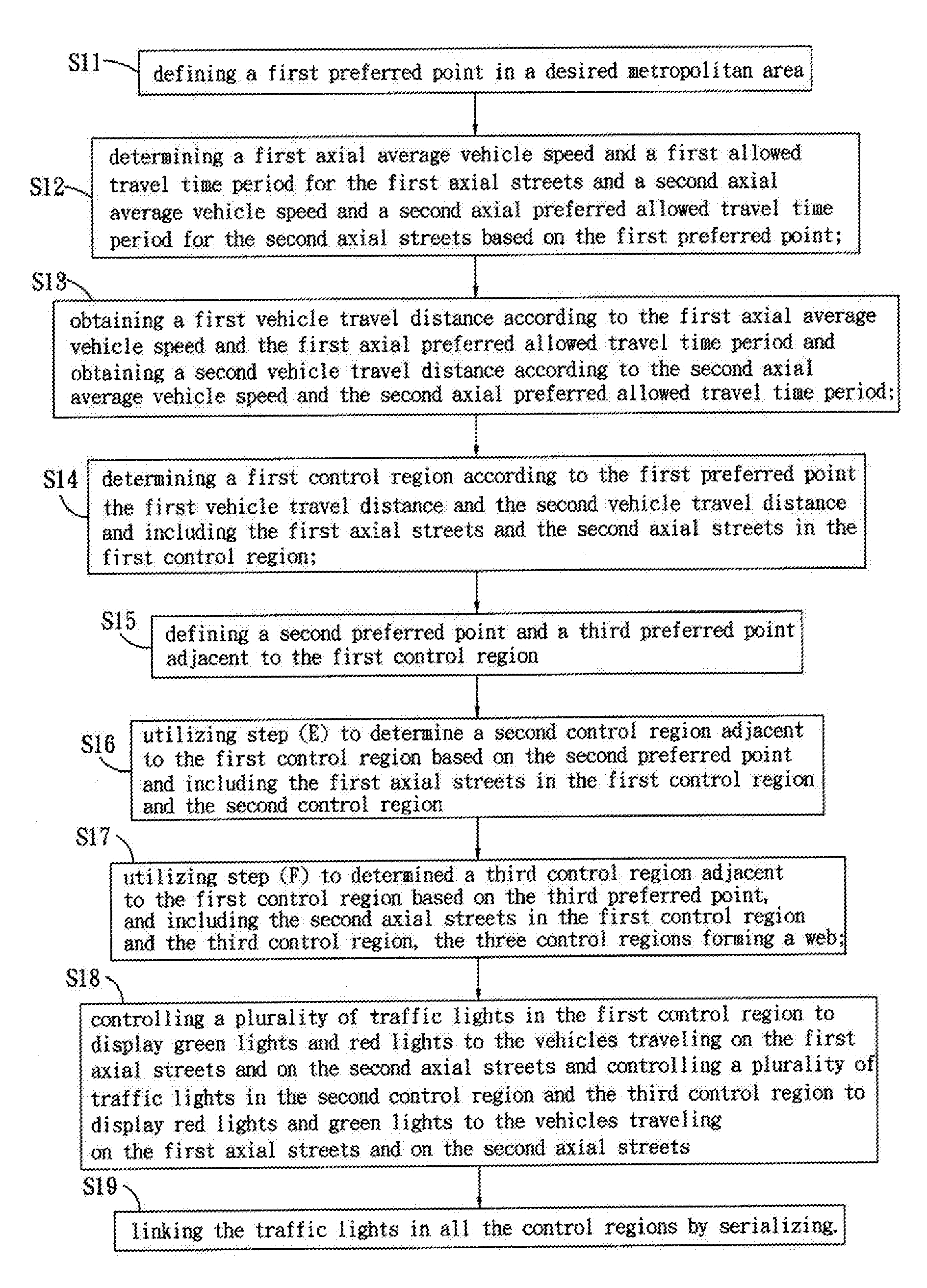
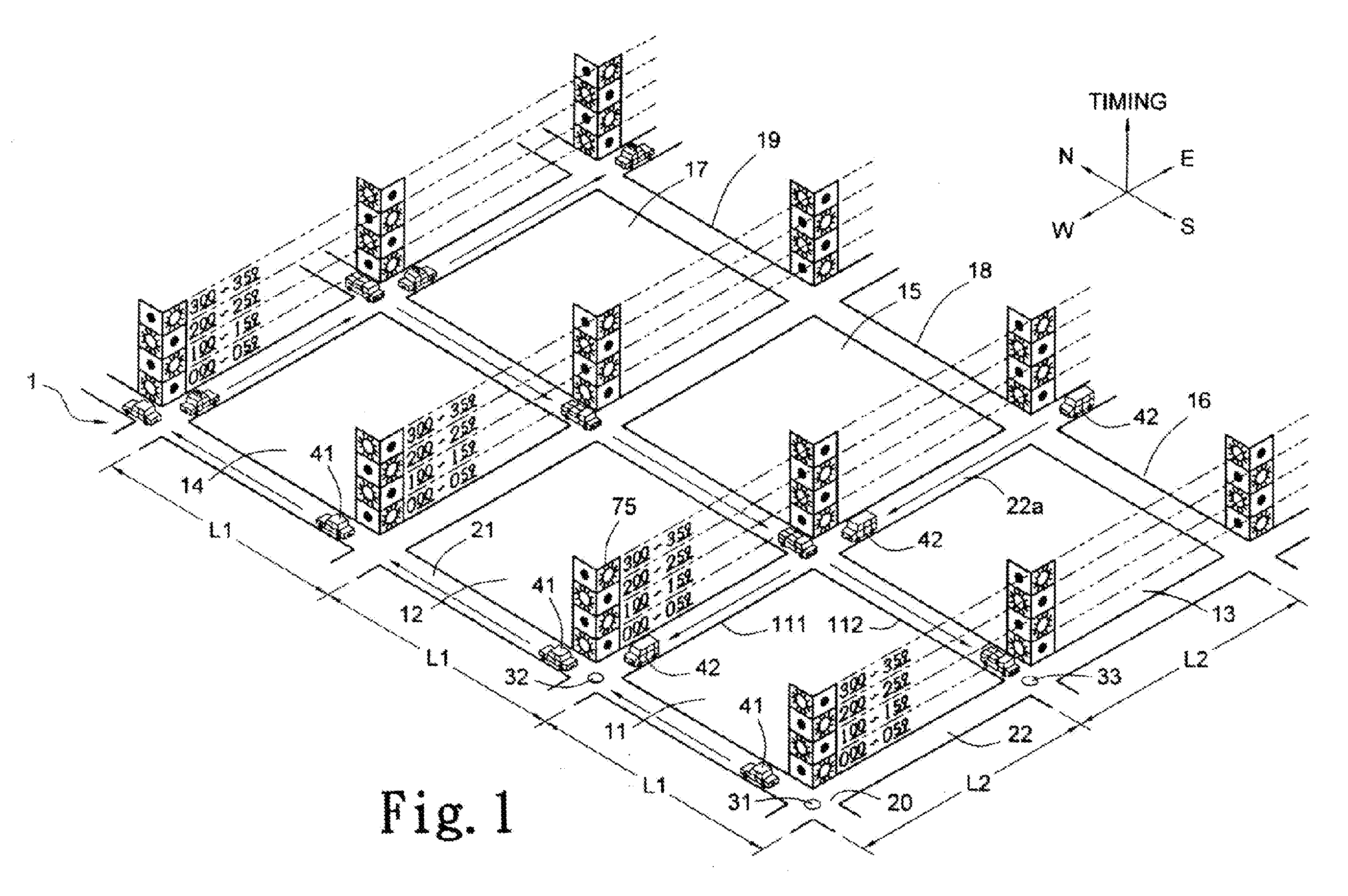
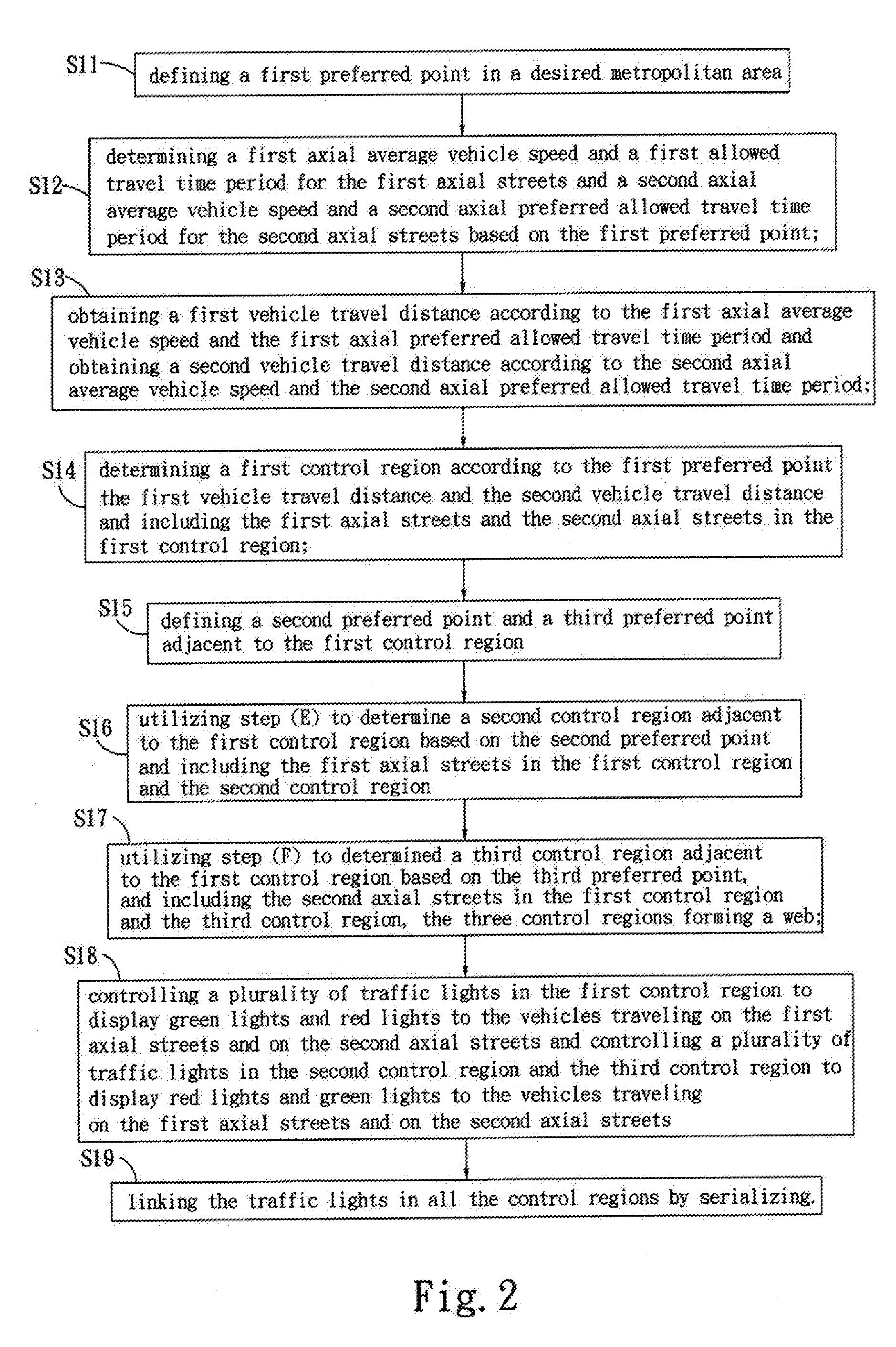
[0050]Please refer to FIG. 1 and FIG. 2. FIG. 1 is a schematic drawing of the present invention. FIG. 2 is a flowchart of an embodiment method of the present invention. In step S11, a first preferred point 31 and a preferred direction are defined in a desired metropolitan area 1, and the desired metropolitan area is divided into a plurality of first axial streets 21 and a plurality of second axial streets 22 based on the first preferred point and the preferred direction. The preferred direction can be geographic east, south, west or north; or it may be a direction of the first axial streets 21 or the second axial streets 22. In this embodiment, the preferred direction is geographic north which is also the direction of the first axial streets 21. The first preferred point 31 can be an intersection or a building. In this embodiment, the first preferred point is an intersection 20 of the first axial streets 21 and the second axial streets 22.

[0051]In step S12, a first axial average veh...

second embodiment

[0066]Please refer to FIG. 6. FIG. 6 is a schematic drawing of the present invention. A local map is divided into first, second, third, fourth, fifth, sixth, seventh, eighth, and ninth control regions 11b, 12b, 13b, 14b, 15b, 16b, 17b, 18b, 19b. Please refer to FIG. 7. All the traffic lights on the first axial streets 21b in the first, fourth, fifth sixth, and ninth control regions 11b, 14b, 15b, 16b, 19b shown in a thick black frame 51 are simultaneously controlled to display green lights and the all the traffic lights on the second axial streets 22b in the same control regions are simultaneously controlled to display red lights. All the traffic lights on the first axial streets 21b in the second, third, seventh, and eighth control regions 12b, 13b, 17b, 18b shown in a thick white frame 52 are simultaneously controlled to display red lights and the all the traffic lights on the second axial streets 22b in the same control regions are simultaneously controlled to display green light...

third embodiment

[0075]Please refer to FIG. 11. FIG. 11 is a schematic drawing of the present invention. The first axial streets 21c are divided into a control region A 61c, a control region B 62c, a control region C 63c, and a control region D 64c. A plurality of traffic light state blocks 75c for the traffic lights 7 are designed for each intersection 20c, and two adjacent blocks. In the left block 75c, the black circle indicates a red light, and in the right block 75 the white circle indicates a green light or a yellow light. Radial lines around the black circle and the white circle indicate that the corresponding traffic light is activated, and the numbers below each control region A 61c (such as 050) indicates a display time for the traffic lights in each control region 61c, 62c, 63c, 64c.

[0076]At the 0th second, two vehicles 41c, 45c respectively move along the first axial streets 21c in the control region A 61c and the control region C 63c; two vehicles 43c, 44c respectively move along the f...


PUM


Abstract

A regional symmetric and interlocked traffic light control method includes: defining a first preferred point in a desired metropolitan area; determining a first axial average vehicle speed and a first axial preferred allowed travel time period for the first axial streets and a second axial average vehicle speed and a second axial preferred allowed travel time period for the second axial streets; obtaining a first vehicle travel distance and a second vehicle travel distance; determining a first control region according to the first preferred point, the first vehicle travel distance and the second vehicle travel distance; defining a second preferred point and a third preferred point adjacent to the first control region; controlling a plurality of traffic lights in the two adjacent control regions to respectively display green and red lights on the same axial streets in accordance with a preferred allowed travel time period and linking the traffic lights in said control regions by serializing. Therefore, a vehicle can pass through a plurality of adjacent control regions in accordance in its cruising speed and the traveling efficiency of the vehicle can be improved.

Description

BACKGROUND OF THE INVENTION[0001]1. Field of the Invention[0002]The present invention relates to a regional symmetric and interlocked traffic light control method, and more particularly to a regional traffic light control method for reducing traffic jams in a plurality of traffic jam control areas for at least two adjacent regions.[0003]2. Description of the Related Art[0004]Currently, traffic lights are commonly used for many intersection in metropolitan areas to control traffic for both vehicles and pedestrians.[0005]A typical traffic light control method for a metropolitan area controls a series of traffic lights along the same direction for a predetermined distance to display a green light or a red light continuously. Therefore, regardless of the traveling speeds of any vehicle, it will have to stop at a red light, which increases travel times. Moreover, when a large number of vehicles all stop and wait for a red light, serious air and noise pollution problems are consequently g...

Claims


Application Information

Patent Timeline
IPC IPC(8): G08G1/081G08G1/08E01F9/00
CPCG08G1/081
Inventor TSAI, HUI-TE
Owner TSAI HUI TE
Features
  • Generate Ideas
  • Intellectual Property
  • Life Sciences
  • Materials
  • Tech Scout
  • Unparalleled Data Quality
  • Higher Quality Content
  • 60% Fewer Hallucinations
Learn More